squares in reel, wliile the squares on the ground arc formed as sawyers mark the intended
path of the saw before sawing up a log of timber ; that is, by stretching cords rubbed
with chalk, ivhich, by being strack ou the ground (previously made perfectly smooth),
leave ivhite lines. >71111 the plan in one hand and a pointed rod in the other, the design
is thus readily traced across these indications. The French and Italians lay out their
most curious partems (Jig. 698.) in this way.
Su b se ct. 2. T ra n s fe rrin g F ig u re s and D esig ns to irre g u la r Surfaces.
2357. S ta kin g o r m a rking out p la n s on irre g u la r surfaces constitutes the most difficult
part of practice, whether in araanging grounds in the countiy, or in laying out streets,
or other improvements in towns. These difficulties do not arise from the intricacy of
the principles of action; bnt from the variety of operations often requisite to overcome
tbe obstructions. They may be all classed nnder three heads; that of transferring a
straight line, a curved line, and a level line.
2358. W here a s tra ig h t line is to be indicated among objects or inequalities not more
than 15 or 20 feet high, its plan or tract on tho eai-th (fig . 699. a . . . h ) may bo
found by the use of poles, a few feet liighcr than the elevation of the obstructions,
the director being placed on a step-ladder or other elevation at one end. »licre this
metliod cannot be adopted on account of the height of the inequalities, the line must
cither be formed along tho summits of these inequalities, ivhich may be done if they are
houses, hills, or trees; or parallel lines (c, d, e) must be formed where practicable, and
the main line found by offsets (/, <7, h ) from those collateral lines at such places as are
suitable. A third method, but one not always perfectly accurate, is to take a plan of
the field or scene of operations, aud on this to set out the proposed line; then, by ascertaining
its bearings and distances relatively to the obstructions, it may be transfeiTcd
from the paper to the ground. In caiTying straight lines through woods, lanterns have
been used ; but a much more correct method is to elevate poles above the surface of the
wood.
2359. Continuous lines may always be made perfectly straight, however iiTcgular the
surface, by following the same parallel as indicated by points of the compass, or by tho
shadow of the operator during sunshine. If the needle docs not move, or the shadow of
the spectator is always projected at the same angle to his course, the direction in wlfich
he walks, in either case, must be straight. The mode of fonning right lines in such
circumstances being understood, the fonnation of right-lined figiures is merely a repetition
of the process, uniting each side by the required angle.
2360. C urved lines on irregular surfaces arc in general only to be laid down by tho
Tirovioas establishment of straight lines ; first, leading straight lines {fig . 682. a, b, c), and
next secondary straight lines {.fig. 682. d, d ), which shall form skeletons to the curves.
A second mode, and on a large scale hy much tho most certain, is to find the leading
points of the cm-vcs by triangles from a knoivn base or known bases; but as botli modes
arc rare in the practice of gardening, they need not be enlarged on.
2361. C ircles, ovals, and every description o f c u rvilin e a r fig u re , may be laid cloivn by
either of the above modes; but, where the obstructions are not great, circles or parts ot
cfrcles may be transfeired more expeditiously by the following method The diameter
of the circle (fig . 700.), and any two points (a and c) wlfich its circumference is to touch,
being given, next ascertain the side of the largest square
wlfich the circle will contain. Then, if the director place
himself in the given point of the cfrcumfcrence, and look
cither throngh the sights of a theodolite, or along the edge of
a common carpenter’s square (d ), or any right-angled boai-d,
the straight line traced by his eye will intersect the situation
of the circumference of the circle ; if he then causes to be
measured, along tbat straight line, the length of the side of
the square contained within the circle, the extent of the
dimension will determine a point in the circumference.
Then looking along the other side of the squ are, or through
the sights of the theodolite at right angles to the fonner _
observation he will by a similar process determine anotlier circumferential point; ancl
now by cliano-ing his position either to the right or left, taking cai-e to set off always
the sarne dimension from the side of the square, he will trace out the circumference ot
the circle, or any portion of it. It is evident to any person
in the slightest degree acquahited with practical geometry,
that the same object may be attained by an adjusted triangle
(such as e), the extremities of which will indicate
points in the circumference ivithout farther trouble. A
very obvious application of this instrument is that of re-
clucino- an irregular basin of water to a circular figure. The
director moves round with the adjusted triangle (Jig.
701. a) ; his assistant sets off the dimensions ; and as each
poiiit in’the circumference is ascertained, it is marked by a
stake ( b ,c ,d ). — O ther modes on s im ila r p rincip les, well
known to land-suiweyors, a re occasionally resorted to in _ _
laying out gardens, especially in the geometric style, and in preparing the foundations
OT oiiTvcd in direction, enn only
be determined on an iraegular surface by measuring doum from an elevated
(a^ or from level lines in parallel directions, and so transferring the points by hori/onUl
levds to the proper line. Straight rods ai-e the ready means of measuring t^o^nwanls,
and the points must be maiked by hillocks or hollows (b ) ; or by smooth-headed stakes
driven into the sui-face, and protruding above, or sunk under it, according to tüe on-
structions.
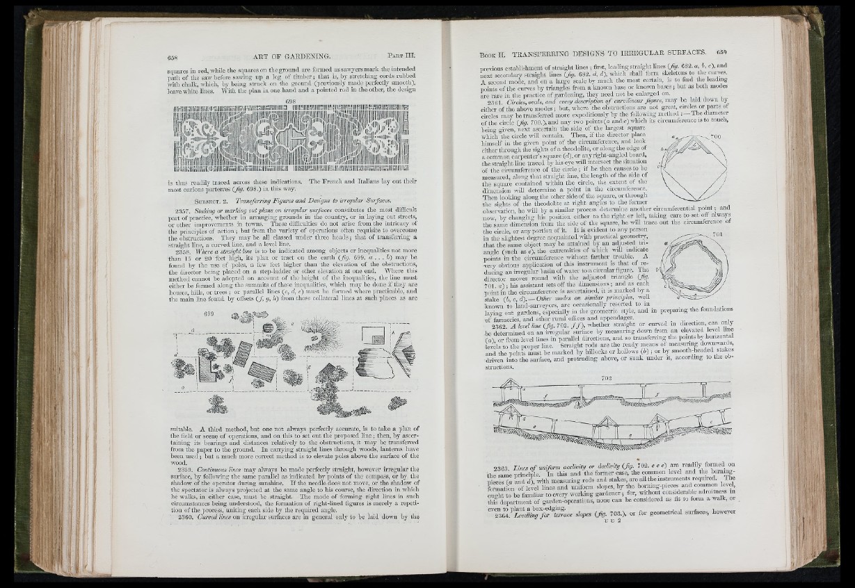
2363. Z iM s o f u n ifo rm a cc lio iiy o r decbmty {fig . 702. e e e) etc reauuy on
the same prmciple. In this and tho former case, the common level and the taimng-
pieces {a and d \ with measuring rods and stakes, are a l U h e instruments required. The
formation of level lines and uniform slopes, by tho bormng-pieoes and common level,
ought to he familiar to every working gardener ; for, ffiT ? l? a °Z d k ot this department of garden-opcrations, none can be considered as fit to foim a walk, 01
slopes {fig . 703.), or for geometrical snrfaces, however
U U 2
■:i i .