along its outer cmh (e). Steam may be produced by pouring water ovei the
the flue (6) ; and also, if desirable, under the bed of earth, hy mtl'oducmg water throu h
a pipe ivith a funnel (A) ; .aU the fines being iui-nished with a COTrse of bricks Mong the
outer edges of the cover, so as to form a trough between them. The m u teo om ( «
is a vault between the two p its ; and, hy means of small o pem np (i), to be closed at
ple.asure by bricks, may receive heat from either or both of t e tbMltVh
most severe ivcatlicr, the warmth incident to its situation wiU be siifficient foi the
o f muslirooms. I t may be fitted up with shelves (A) m t e usual way ; and may also
be used for forcing succory, rhubai’b, sea kale, winter potatoes, &c.
2008. KemlaU’s double p it (fig. 667.) has hollow walls, 12 m thick at t e base (a)
and 7 ft. h ig h ; t e hack of the wall is huilt perpendicular (o 6), with common b u c k s ,
and t e inner part (c d) is hnilt of what are called flooring-hricks, which ai'e only about
2 in thick. The cross pai-titions which connect the two walls together are also built ot
these flooring-biicks, .set on edge. Tlie inner part of the l ÿ l beve s, or approaches o
t e outer part of the wall, from the base to t e height of 4 ft. (e), where it is reduced to
9 iu. in thiekness, at which width it is continued to the top. Immediately above the
intended depth of t e soil of the pit ( f ) , a course of bricks on edge is left out both
in t e back and front walls of t e pit ; and t e walls are covered from one end to the
other, hy a course of slates or tiles, 9 in. wide (g). Above this t e wall is continued
hollow to t e top, where it is furnished with a stone or wooden coping, m the usual
way. The mould of t e pit is supported by cross-bars of cast u-on, let into the back
and front walls, on which may he laid old boards, branches of fir and straw, pea-sticky
or turves, as may ho most convenient. The ft'ont wall of t e one pit (Ay and " 7
wan of t e other (i), are built bevelling on both sides. Tlie front waU of th® second
nit (A) requfres no description ; hut it is necessaiy to observe, that this second pit should
be a foot lower in the soü than t e hack one, in order that t e latter may not he shaded
by it. The space between the pits (1) is for the piupose of appljmig a hning to heat
both pits ; it is covered with hoards, which incline to one side, and form a gutter at their
lower angle (m) for cimying oif the rain. In veiy severe weather, luungs of litter (p)
may be used to protect those pai-ts of t e waUs which are above ground. These pits are
intended to he heated hy dung or any other fermenting substance, introduced mto the
vault from doors at one or hoth ends. Whüe this fementing substance supplies a moist
heat to t e eaith over it, it will also supply a dry heat to the hollow side walls ; which
heat vrill enter the atmosphere round the plants by the openings ( / g) under the course
of tiles or slates (p). The moist heat, if desirable, might easily be admitted by direct
communications through the soil to the vault, made by a few bncks, a chimncy-pot, or a
whelmed flower-pot. Ventilators may be formed in the doors at each end for supplymg
cool air, in case of too great a heat in the v a u lt; and plugs or wooden blocks, with rings
for convement handling, may be placed in one or tivo places in the back and front walls,
to admit, through the hot vacuity, fresh air to the plauts in very severe weather. As the
outer surface of the end walls wiU be fully exposed to the weather, they should not
communicate with the side walls, but should form distmct hollow walls of themselves;
and, in order to prevent the escape of heat from the outer surface of the back and front
walis, a space, of a foot or more, between them and the soil in whicli they are sunk,
should be fiUed up with loose stones or brickbats (n).
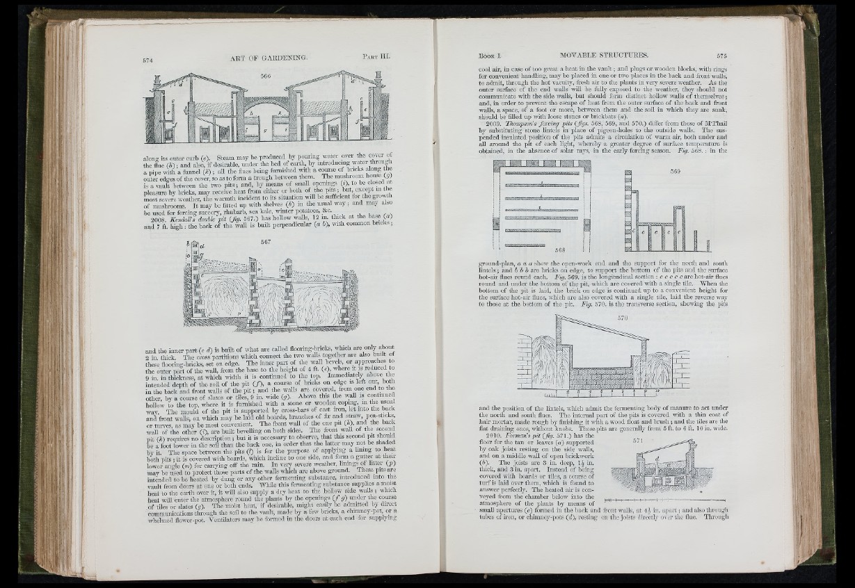
2009. Tkompsoiis forcing pits (figs. 568, 569, and 570.) differ from those of M ‘Phail
by substituting stone lintels in place of pigeon-holes to the outside walls. The suspended
insulated position of the pits admits a circulation of warm air, both under and
all around the pit of each light, whereby a g-reatcr degree of surface temperature is
obtained, in the absence of solar rays, in the early forcing season. Fig. 568.: in the
ground-plan, a a a show the open-work end and the support for the north and south
lintels ; and b b h are bricks on edge, to support the bottom of the pits and the surface
hot-air flues round each. Fig. 569. is the longitudinal section : c c c c c are liot-air flues
round and under the bottom of the pit, which are covered with a single tile. Wlien the
bottom of the pit is laid, the brick on edge is continued up to a couveiiient lieight for
the surface hot-air flues, which are also covered with a single tile, laid the reverse way
to those at the bottom of the pit. Fig. 570. is the transverse section, showing the pits
and. the position of the lintels, wliich admit the fermenting body of manure to act under
the nortli and south flues. The internal pai't of the pits is covered with a thin coat of
hah* mortar, made rough by finishing it with a wood float and b ru sh ; and the tiles ave the
flat draining ones, without knobs. These pits arc generally from 5 ft. to 6 ft. 10 in. wide.
2010. Forman’s p it (fig. 571.) has the
floor for the tan or leaves (a ) supported
hy oak joists resting on the side walls,
and on a middle wall of open brickwork
(b). The joists are 3 in. deep, 1^ in.
thick, and 3 in. apart. Instead of being
covered with boards or tiles, a course of
tu rf is laid over them, which is found to
answer perfectly. The heated air is conveyed
from the chamber below into the
atmosphere of the plants by means of
small apertures (e) formed in the back and front walls, at 4^ in. a p a rt; and also through
tubes of iron, or chimney-pots (d), resting on the joists directly over the flue. Through
. M
( ■ ' f -I
i'. ' il
I' f: • -I