This apparatus is to show the composition of two harmonic
motions at right angles to each other. It was first shown to the public
on New Years Day 1874 at the Post Office Soirée. The editor of
Engineering wrote: “One of the features of the evening [was] Tisleys
Compound Pendulum Apparatus, and by its beauty and perfect harmony
attracted much attention”. On 6 February a note was published:
“Tisleys Compound Pendulum”, where it was pointed out that hitherto
Lissajous’ figures were transient, whereas now there was a permanent
record.
A.E. Donkin, a Fellow of Exeter College, Oxford, may have
been the originator of this device or just a spokesman, since he gave a
paper to the British Association for the Advancement of Science at
Bradford in 1873. He ended with this sentence^iThe instrument is
constructed by Messrs. Tisley and Spiller, of Brompton Road, to whom
several improvements on the original model are due”. The editor of
Ganot’s Physics (1906) wrote that: “Tisleys Compound Pendulum apparatus
or Harmonograph is one of the best...” The two pendulums, fit-
.7 2 , B r o m p t o n . R o a d ,
3 M IN U T C S W A L K F R O M K E N S I N C T Q N M U S E U M .
S M IN U T E S W A L K F R O M T H E E X H I B I T IO N OH SO U TH K E N S IN G T O N S TA T IO N .
r'taclmcch S'
382
I 1
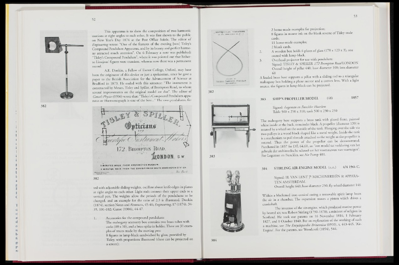
ted with adjustable sliding weights, oscillate about knife-edges in planes
at right angles to each other. Light rods connect their upper ends to a
vertical pen. The weights allow the periods of the pendulums to be
changed, and an example for the ratio of 2:3 is illustrated. Donkin
(1874), section Notes and Abstracts, 45-46; Engineering, 17;|1874), 3#t
35, 101-102; Ganot (1906), 44-47.
1. Accessories for the compound pendulum:
The mahogany accessory box contains two brass tubes with
. corks (88 x 10), and a brass'Hjike in holder. There are 31 examples
of traces made by the moving pen:
8 figures in lamp-black sandwiched by glass, provided by
Tisley, with proportions illustrated (these can be projected on
a screen);
RECTINIoÙlAH VIBRATIONS
I fi THE PROPORTION o k g '• 3 ' I
T i s l e y i s Com poun d p en d u lu m
APPARATUS.
2 home-made examples for projection;
8 figures in mauve ink on the blank reverse of Tisley trade
cards;
11 home-made examples;
2 blank cards.
2. A wooden box holds 6 plates of glass (178 x 123 x 3), one
coated with lamp-black.
3. Overhead projector for use with pendulum:
Signed: TISLEY & SPILLER 172 Brompton &W LONDON
Overall height of pillar 440; base diameter 108; lens diameter
68
A leaded brass base supports a pillar with a sliding rod to a triangular
mahogany box holding a plane mirror and a convex lens. With a light
source, the figures in lamp-black can be projected.
383 SHIP’S PROPELLER MODEL j§(48) 1857
Signed: Logeman en Funckler Haarlem
Table 500 x 250 x 310; tank 500 x 230 x 250
The mahogany base supports a brass tank with glazed front, painted
white inside at the back, remainder black. A propeller (diameter 130) is
rotated by a wheel on the outside of the tank. Hanging over the side via
two pulleys is a wood block shaped like a metal weight. Inside the tank
is a mechanism to pull threads attached to the weight as the propeller is
rotated. Thus the power of the propeller can be demonstrated.
Purchased in 1857 for Dfl. 64.60, as: “een model ter verklaring van het
gebruik der archimedische schroef tot het voortstuwen van vaartuigen”.
For Logeman en Funckler, see Air-Pump 401.
384 STIRLING AIR-ENGINE MODEL ( n . n || 4/4 19th C.
Signed: H. VAN LENT ]R MACHINERIEEN & APPARA-
TEN AMSTERDAM.
Overall height 640; base diameter 250; fly-wheel diameter 146
Within a blackened iron conical casing a removable spirit lamp heats
the air in a chamber. The expansion moves a piston which drives a
crankshaft.
The inventor of the air-engine, which produced motive power
by heated ait, was Robert Stirling (1790-1878), a minister of religion in
Scotland. He took out patents on 16 November 1816, 1 February
1827, and 1 October 1840. For an explanation of the working of such
a machine, see The Encyclopaedia Britannica (1||10), I, 443-445, Air-
Engine’. For the patents; See Woodcroft (1854), 544.