694 DYNAMO-ELECTRIC MACHINE (700) 1870
Table 1,500 x 600 x 915 high; wheel 930
A large table has mounted within it a large iron wheel with handle, and
a leather belt connecting it to the Siemens-type armature. The drive
rotates an axle with four and two coils. The field is provided by the electro
magnet, in two sections (each: width 250, thickness 45, height
210), mounted on a board. The electro-magnets are highly magnetized
by the rotation of one set of coils, while the other armature becomes
excited and produces an electric current in an external circuit. A commutator
at the end of the axle changes AC to DC, so making this one
of the first machines to produce a strong direct current. This form of
auto-excitation (or dynamo) was developed by Henry Wilde and
William Ladd; the Ladd version is exhibited here; see Ladd (1867). It
was invoiced by P.J. Kipp en Zonen on 2 December 1870 for Dfl
356.50. On the same table is the Gramme dynamo (695). Deschanel
(1877), 771-774, fig. 560; Guillemin (1891), 414, fig. 276; Ernecke
[1905], 325, fig. 8982.
694
695 DYNAMO-ELECTRIC MACHINE (702) 1881
Signed: GRAMME. INV. BREVETE S.G.D.G. BREGUETJ
P N° 696.
Baseboard 330 x 370; overall height to top of iron arch 610;
coil diameter 124
The brass frame is screwed to the mahogany baseboard. The permanent
magnet is composed of four leaves. Between the polls rotates a ring of
soft iron bound with insulated copper wire. This generator is capable of
producing direct current electricity. EW. Funckler s invoice of January
1882 is for Dfl. 386.40.
Zénobe Théophile Gramme (1826-1901), a Belgian model
maker, invented this efficient generator in 1869. A Gramme machine as
here, with the serial number 465, is in the Museum of the History of
Science, Oxford. See Z.T. Gramme, “Sur une machine magnéto-électrique
produisant des courants continus”, Comptes Rendus, 73 (1871),
175-178. Deschanel (18P#)r773*-774*; Guillemin (1891), 409-412,
fig. 275.
695 694 (front) 695 (back)
Induction Coils
696 INDUCTION COIL (683) 1861
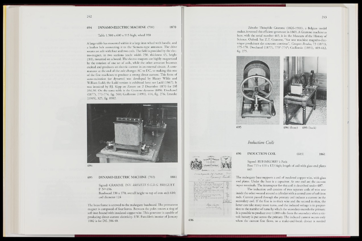
696
Signed: RUHMKORFF á Paris
Base 715 x 410 x 123 high; length of coil with glass end plates
645
The mahogany: base supports a coil of insulated copper wire, with glass
end plates. Under the base is a capacitor. At one end are the current
input terminals. The interruptor for this coilws described under 697.
The induction coil consists of two separate coils of wire one
inside the other wound around a cylinder with a central core of soft iron
rods. Current passed through the primary coil induces a current in the
secondary coil. If the first is in thick wire and the second in thin, the
latter can take many more turns, and the induced voltage is in proportion
to the number of turns by which the secondary exceeds the primary.
It is possible to produce over 1,000 volts from the secondary when a six-
volt battery is put across the primary. The induced current occurs only
when the current first flows, so a make-and-break device is needed