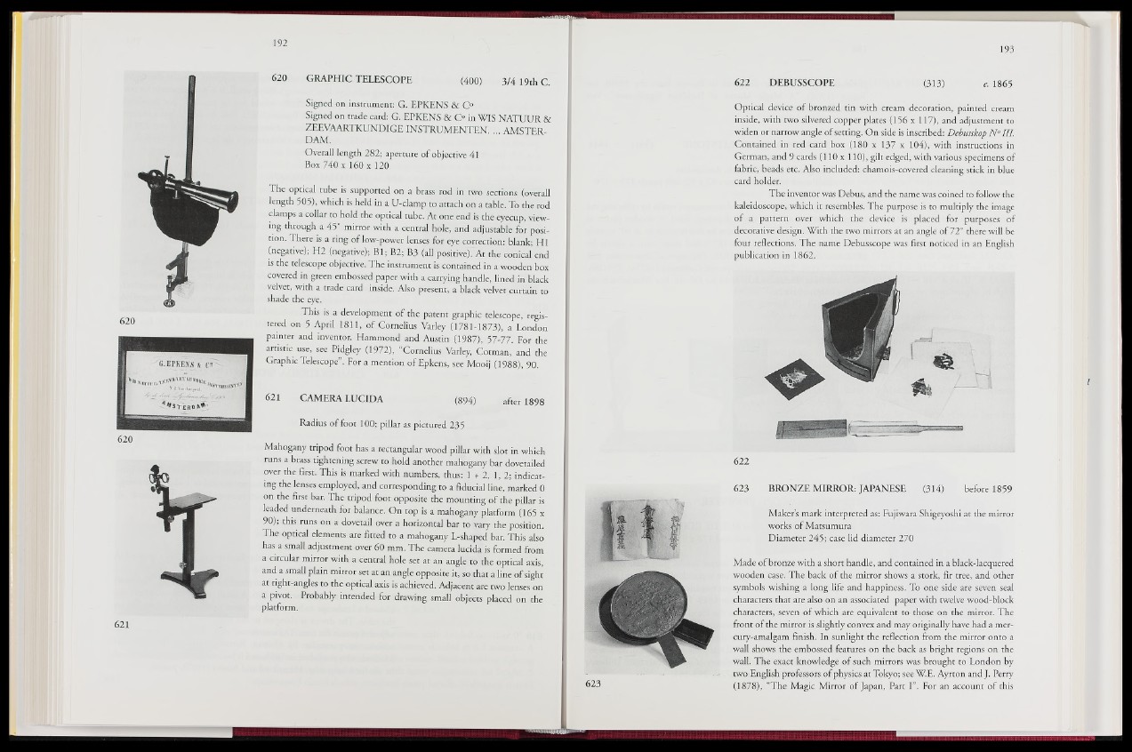
620 GRAPHIC TELESCOPE (400) 3/4 19th C.
620
620
Signed on instrument: G. EPKENS & C°
Signed on trade card: G. EPKENS & C° in WIS NATUUR &
ZEEVAARTKUNDIGE INSTRUMENTER ... AMSTERDAM.
Overall length 282; aperture of objective 41
Box 740 x 160 x 120
The optical tube is supported on a brass rod in two sections (overall
length 505), which is held in a U-clamp to attach on a table. To the rod
clamps a collar to hold the optical tube. At one end is the eyecup, viewing
through a 45° mirror with a central hole, and adjustable for position.
There is a ring of low-power lenses for eye correction: hlank- HI
(negative); H2 (negative); Bl; B2; B3 (all positive). At the conical end
is the telescope objective. The instrument is contained in a wooden box
covered in green embossed paper with a carrying handle, lined in black
velvet, with a trade card inside. Also present, a black velvet curtain to
shade the eye.
This is a development of the patent graphic telescope, regis-
tered on 5 April 1811, of Cornelius Varley (1781-1873), a London
painter and inventor. Hammond and Austin (1987), 57-77. For the
artistic use, see Pidgley (1972), “Cornelius Varley, Cotman, and the
Graphic Telescope”. For a mention ofEpkens, see Mooij (1988), 90.
621 CAMERA LUCIDA (894) after 1898
Radius of foot 100; pillar as pictured 235
Mahogany tripod foot has a rectangular wood pillar with slot in which
runs a brass tightening screw to hold another mahogany bar dovetailed
over the first. This is marked with numbers, thus:. 1 + 2, 1, 2; indicating
the lenses employed, and corresponding to a fiducial line, marked 0
on the first bar. The tripod foot opposite the mounting of the pillar is
leaded underneath for balance. On top is a mahogany platform (165 x
90); this runs on a dovetail over a horizontal bar to vary the position.
The optical elements are fitted to a mahogany L-shaped bar. This also
has a small adjustment over 60 mm. The camera lucida is formed from
a circular mirror with a central hole set at an angle to the optical axis,
and a small plain mirror set at an angle opposite it, so that a line of sight
at right-angles to the optical axis is achieved. Adjacent are two lenses on
a pivot. Probably intended for drawing small objects placed on the
platform.
622 DEBUSSCOPE (313) c. 1865
Optical device of bronzed tin with cream decoration, painted cream
inside, with two silvered copper plates (156 x U p la n d adjustment to
widen or narrow angle of setting. On side is inscribed: Debusskop N ° III.
Contained in red card box (180 x 137 x 104),-with instructions in
German, and 9 cards (110x110), gilt edged, with various specimens of
fabric, beads etc. Also included: chamois-covered cleaning stick in blue
card holder.
The inventor was Debus, and the name was coined to follow the
kaleidoscope, which it resembles. The purpose is to multiply the image
of a pattern over which the device is placed for purposes of
decorative design. With the two mirrors at an angle of 72° there will be
four reflections. The name Debusscope was first noticed in an English
publication in 1862.
622
623 BRONZE MIRROR: JAPANESE (314) before 1859
Makers mark interpreted as: Fujiwara Shigeyoshi at the mirror
works of Matsumura
Diameter 245; case lid diameter 270
Made of bronze with a short handle, and contained in a black-lacquered
wooden case. The back of the mirror shows a stork, fir tree, and other
symbols wishing a long life and happiness. To one side are seven seal
characters that are also on an associated paper with twelve wood-block
characters, seven of which are equivalent to those on the mirror. The
front of the mirror is slighdy convex and may originally have had a mer-
cury-amalgam finish. In sunlight the reflection from the mirror onto a
wall shows the embossed features on the back as bright regions on the
wall. The exact knowledge of such mirrors was brought to London by
two English professors of physics at Tokyo; see W.E. Ayrton and J. Perry
(1878), “The Magic Mirror of Japan, Part I”. For an account of this