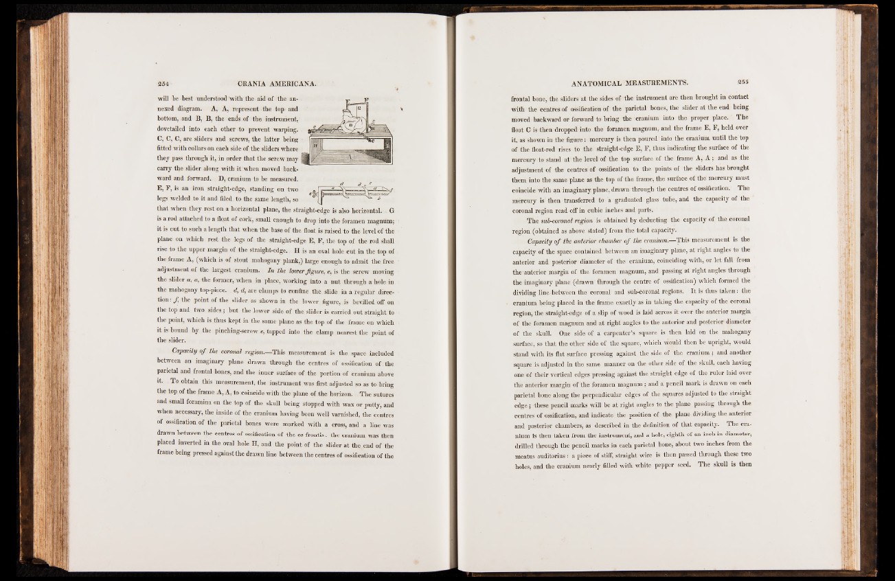
will be best understood with the aid of the annexed
diagram. A, A, represent the top and
bottom, and B, B, the ends of the instrument,
dovetailed into each other to prevent warping.
C, C, C, are sliders and screws, the latter being
fitted with collars on each side of the sliders where
they pass through it, in order that the screw may )
carry the slider along with it when moved backward
and forward. D, cranium to be measured.
E, F, is an iron straight-edge, standing on two
legs welded to it and filed to the same length, so
that when they rest on a horizontal plane, the straight-edge is also horizontal. G
is a rod attached to a float of cork, small enough to drop into the foramen magnum;
it is cut to such a length that when the base of the float is raised to the level of the
plane on which rest the legs of the straight-edge E, F, the top of the rod shall
rise to the upper margin of the straight-edge. II is an oval hole cut in the top of
the frame A, (which is of stout mahogany plank,) large enough to admit the free
adjustment of the largest cranium. I n the lower fig u re , c, is the screw moving
the slider a, a, the former, when in place, working into a nut through a hole in
the mahogany top-piece, d, d, are clamps to confine the slide in a regular direction:
f the point of the slider as shown in the lower figure, is bevilled off on
the top and two sides; but the lower side of the slider is carried out straight to
the point, which is thus kept in the same plane as the top of the frame on which
it is bound by the pinching-screw e, tapped into the clamp nearest the point of
the slider.
Capacity o f the coronal region.—-This measurement is the space included
between an imaginary plane drawn through the centres of ossification of the
parietal and frontal bones, and the inner surface of the portion of cranium above
it. To obtain this measurement, the instrument was first adjusted so as to bring
the top of the frame A, A, to coincide with the plane of the horizon. The sutures
and small foramina on the top of the skull being stopped with wax or putty, and
when necessary, the inside of the cranium having been well varnished, the centres
of ossification of the parietal bones were marked with a cross, and a line was
drawn between the centres of ossification of the os frontis: the cranium was then
placed inverted in the oval hole H, and the point of the slider at the end of the
frame being pressed against the drawn line between the centres of ossification of the
frontal bone, the sliders at the sides of the instrument are then brought in contact
with the centres of ossification of the parietal bones, the slider at the end being
moved backward or forward to bring the cranium into the proper place. The
float C is then dropped into the foramen magnum, and the frame E, F, held over
it, as shown in the figure: mercury is then poured into the cranium until the top
of the float-rod rises to the straight-edge E, F, thus indicating the surface of the
mercury to stand at the level of the top surface of the frame A, A ; and as the
adjustment of the centres of ossification to the points of the sliders has brought
them into the same plane as the top of the frame, the surface of the mercury must
coincide with an imaginary plane, drawn through the centres of ossification. The
mercury is then transferred to a graduated glass tube, and the capacity of the
coronal region read off in cubic inches and parts.
The sub-coronal region is obtained by deducting the capacity of the coronal
region (obtained as above stated) from the total capacity.
Capacity o f the anterior chamber o f the cranium.—This measurement is the
capacity of the space contained between an imaginary plane, at right angles to the
anterior and posterior diameter of the cranium, coinciding with, or let fall from
the anterior margin of the foramen magnum, and passing at right angles through
the imaginary plane (drawn through the centre of ossification) which formed the
dividing line between the coronal and sub-coronal regions. It is thus taken: the
cranium being placed in the frame exactly as in taking the capacity of the coronal
region, the straight-edge of a slip of wood is laid across it over the anterior margin
of the foramen magnum and at right angles to the anterior and posterior diameter
of the skull. One side of a carpenter’s square is then laid on the mahogany
surface, so that the other side of the square, which would then be upright, would
stand with its flat surface pressing against the side of the cranium ; and another
square is adjusted in the same manner on the other side of the skull, each having
one of their vertical edges pressing against the straight edge of the ruler laid over
the anterior margin of the foramen magnum; and a pencil mark is drawn on each
parietal bone along the perpendicular edges of the squares adjusted to the straight
edge; these pencil marks will be at right angles to the plane passing through the
centres of ossification, and indicate the position of the plane dividing the anterior
and posterior chambers, as described in the definition of that capacity. The cranium
is then taken from the instrument, and a hole, eighth of an inch in diameter,
drilled through the pencil marks in each parietal bone, about two inches from the
meatus auditorius: a piece of stiff, straight wire is then passed through these two
holes, and the cranium nearly filled with white pepper seed. The skull is then