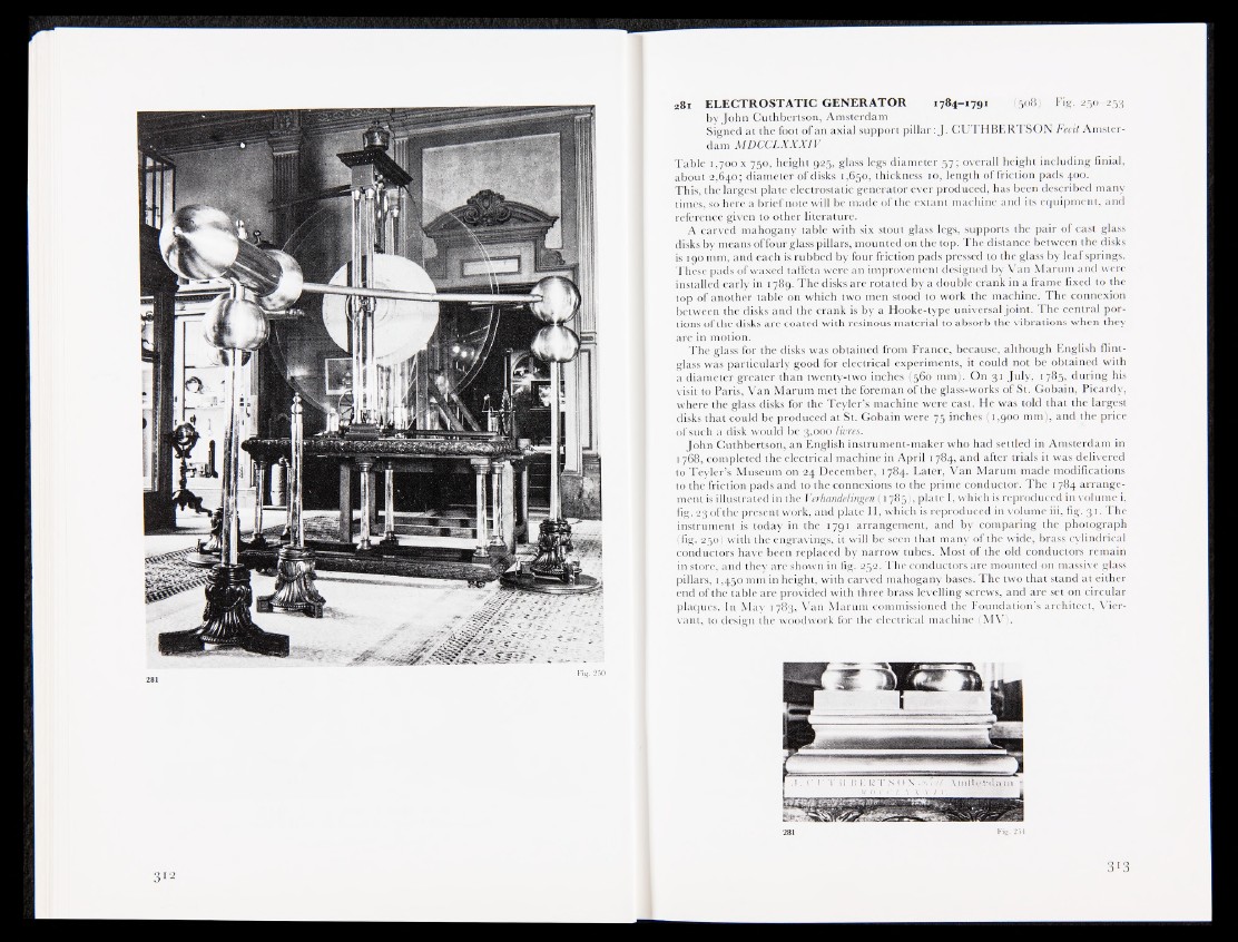
28 i ELECTROSTATIC GENERATOR 1784-1791 (508) Fig. 250-253
by John Cuthbertson, Amsterdam
Signed at the foot of an axial support pillar: J. CUTHBERTSON Fecit Amsterdam
MDCCLXXX1V
Table 1,700 x 750, height 925, glass legs diameter 57; overall height including finial,
about 2,640; diameter of disks 1,650, thickness 10, length of friction pads 400.
This, the largest plate electrostatic generator ever produced, has been described many
times, so here a brief note will be made of the extant machine and its equipment, and
reference given to other literature.
A carved mahogany table with six stout glass legs, supports the pair of cast glass
disks by means of four glass pillars, mounted on the top. The distance between the disks
is 190 mm, and each is rubbed by four friction pads pressed to the glass by leaf springs.
These pads of waxed taffeta were an improvement designed by Van Marum and were
installed early in 1789. The disks are rotated by a double crank in a frame fixed to the
top of another table on which two men stood to work the machine. The connexion
between the disks and the crank is by a Hooke-type universal joint. The central portions
of the disks are coated with resinous material to absorb the vibrations when they
are in motion.
The glass for the disks was obtained from France, because, although English flint-
glass was particularly good for electrical experiments, it could not be obtained with
a diameter greater than twenty-two inches (566 mm). On 31 July, 1785, during his
visit to Paris, Van Marum met the foreman of the glass-works of St. Gobain, Picardy,
where the glass disks for the Teyler’s machine were cast. He was told that the largest
disks that could be produced at St. Gobain were 75 inches (1,900 mm), and the price
of such a disk would be 3,000 livres.
John Cuthbertson, an English instrument-maker who had settled in Amsterdam in
1768, completed the electrical machine in April 1784, and after trials it was delivered
to Teyler’s Museum on 24 December, 1784. Later, Van Marum made modifications
to the friction pads and to the connexions to the prime conductor. The 1784 arrangement
is illustrated in the Verhandelingen (1785), plate I, which is reproduced in volume i,
fig. 23 of the present work, and plate II, which is reproduced in volume iii, fig. 31. The
instrument is today in the 1791 arrangement, and by comparing the photograph
(fig. 250) with the engravings, it will be seen that many of the wide, brass cylindrical
conductors have been replaced by narrow tubes. Most of the old conductors remain
in store, and they are shown in fig, 252. The conductors are mounted on massive glass
pillars, 1,450 mm in height, with carved mahogany bases. The two that stand at either
end of the table are provided with three brass levelling screws, and are set on circular
plaques. In May 1783, Van Marum commissioned the Foundation’s architect, Vicr-
vant, to design the woodwork for the electrical machine (MV).