2 4 3 I'iK. 210
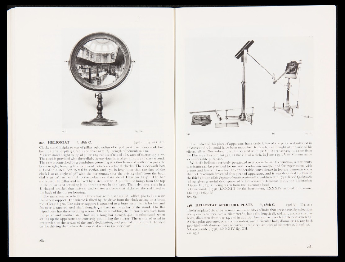
245 HELIOSTAT 3/4 18th C. (308* Fi&;2i 1, 212
Clock: stand height to top of pillar 196, radius of tripod 90 & 105, clockwork box,
face 125 x 71, depth 38, radius of drive arm 158, length of pendulum .310.
Mirror: stand height to top of pillar 224, radius of tripod 167, area of mirror 117 x 77.
The clock is provided with three dials, twenty-four hour, sixty minute and sixty second.
The rate is controlled by a pendulum consisting of a thin brass rod with an adjustable
brass weight, hanging from a thread between cycloidal cheeks. The clockwork box
is fixed to a steel bar 19 x 6 in section and 170 in length, so that the face of the
clock is at an angle of 38° with the horizontal; thus the driving shaft from the hour
dial is at 52^ or parallel to the polar axis (latitude of Haarlem tj2.4.°wThe bar
slides into the pillar and is fixed by a steel screw. A plumb line hangs from the top
of the pillar, and levelling is by three screws in the base. The drive arm ends in -a
U-shaped bracket that swivels, and carries a sleeve: that slides on the rod fixed to
the back of the mirror housing.
1'he metal mirror is held in a brass tray with a sliding lid, which pivots in a wide
U-shaped support. The mirror is tilted by the drive from the clock acting on a brass
rod of length 370. The mirror support is attached to a brass stem that is hollow and
fits over a tapered steel shaft (length 57) fixed in the pillar of the stand. The flat
tripod base has three levelling screws. The stem holding the mirror is removed from
the pillar and another stem holding a long bar (length 44o|pis substituted when
setting up the apparatus and correctly positioning the mirror. The arm is adjusted in
proportion to the secant of the sun’s declination, and pointed to the tip of the style
on the driving shaft when the hour dial is set in the meridian.
2 46 2 « FiS -2U
The maker of this piece of apparatus has closely followed the pattern illustrated in
’s Gravesande. It could have Ben made for Dr. Bosch, and bought at the sale of his
effects, 18-19 November, 1789, by Van Marum (MV). Alternatively, it came from
the Ebeling collection, lot 0;|2:, at the sale of which, in June 1791, Van Marum made
a considerable purchase.
With the heliostat correctly positioned in a box in front of a window, a stationary
sun-beam can-be provided for use with a solar microscope, and for experiments with
prisms and lenses. It was for the considerable convenience in lecture-demonstrations
that ’s Gravesande invented this piece of apparatus, and it was described by him in
the third edition of his Physices elementa mathematica, published in 1742. Rees’ Cyclopaedia
(1819) gives a useful description o f ’s Gravesande’s heliostat (r.zj.), the illustration
(Optics VI, fig. 1) being taken from the inventor’s book.
’s Gravesande (1748) LXXXIII for the instrument, LXXXIV as used in a room;
Ebeling (1789) 66.
Ini. 6511
246 HELIOSTAT APERTURE PLATE 3/4 18th C. (308/c) Fig. 211
The brass plate (169 x 1 o 1) is made with a number of holes that are covered by selections
of stops and shutters. A disk, diameter 80, has a slit, length 18, width 1, and six circular
holes, diameters from 1 to 14, and in addition bears an arm with a hole of diameter 1.
A triangular aperture, 20 x 5 at its widest, and a circular hole, diameter 11, are both
provided with shutters. An arc carries three circular holes of diameter 2, 6 and 12.
’s Gravesande (1748) LXXXIV fig. GH.
Inv. 6511