2 10
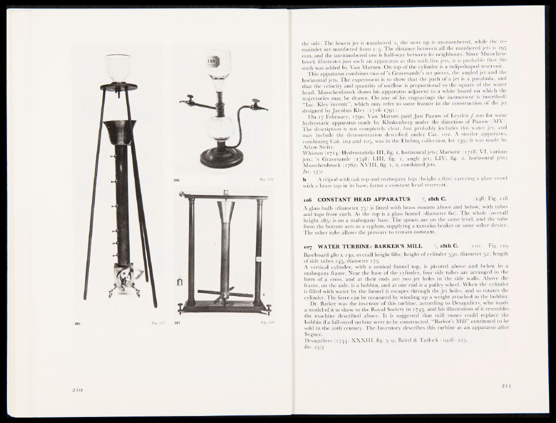
the side. The lowest jet is numbered i, the next up is un-numbered, while the remainder
are numbered from 2—5' The distance between all the numbered jets is 195
mm, and the un-numbered one is half-way between its neighbours. Since Musschen-
broek illustrates just such an apparatus as this with five jets, it is probable that the
sixth was added by Van Marum. On top of the cylinder is a tulip-shaped reservoir.
This apparatus combines two o f ’s Gravesande’s set pieces, the angled jet and the
horizontal jets. The experiment is to show that the path of a jet is a parabola, and
that the velocity and quantity of outflow is proportional to the square of the water
head. Musschenbroek shows his apparatus adjacent to a white board on which the
trajectories may be drawn. On one of his engravings the instrument is inscribed:
“ lac. Kley invenit” , which may refer to some feature in the construction of the jet
designed by Jacobus Kley (1716-1791).
On 17 February, 1790, Van Marum paid Jan Paauw of Leyden ƒ 200 for some
hydrostatic apparatus made by Klinkenberg under the direction of Paauw (MV).
The description is not completely clear, but probably includes this water jet, and
may include the demonstration described under Cat. 102. A similar apparatus,
combining Gat. t@S and 105; was in the Ebeling collection, lot 139; it was made by
Adam Steh-JfflHI
Whiston (1714) Hydrostaticks III, fig. 1, horizontal jets; Mariotte (1718) VI, various
jets; ’s Gravesande l( 1748«LIII, fig. 1, angle jet; LIV, fig. 2, horizontal jets;
Musschenbroek (17623! XVIII, fig. 1, 2, combined jets.
Inv. 13/2
b A tripod with oak top and mahogany legs (height 1,670) carrying a glass vessel
with a brass tap in its base, forms a constant head reservoir.
106 CONSTANT HEAD APPARATUS >„ 18th C. (148) Fig. 118
A glass bulb (diameter 75) is fitted with brass mounts above and below, with tubes
and taps from each. At the top is a glass funnel (diameter 60). The whole (overall
height 285! l i o n a mahogany base. The SipOuts are on the same level, and the tube
from the bottom acts as a syphon, supplying a tantalus beaker or some other device.
The other tube allows the pressure to remain constant.
107 WATER TURBINE: BARKER’S MILL 3/4 18th C. ( no) Fig. 119
Baseboard 480 x 130, overall height 680; height of cylinder 550, diameter 52; length
of side tubes 145, diameter 175.
A vertical cylinder, with a conical funnel top, is pivoted above and below in a
mahogany frame. Near the base of the cylinder, four side tubes are arranged in the
form of a cross, and at their ends are two jet holes in the side walls. Above the
frame, on the axle, is a bobbin, and at one end is a pulley wheel. When the cylinder
is filled with water by the funnel it escapes through the jet holes, and so rotates the
cylinder. The force can be, measured by winding up a weight attached to the bobbin.
Dr. Barker was the inventor of this turbine, according to Desaguliers, who made
a model of it to show to the Royal Society in 1743, an<^ bis illustration of it resembles
the machine described above. It is suggested that mill stones could replace the
bobbin if a full-sized turbine were to be constructed. “Barker’s Mill” continued to be
sold in the 20th century. The Inventory describes this turbine as an apparatus after
Segner.
DesaguliersrBi744) XXXIII, fig. 5—9; Baird & Tatlock (1928) 225.
H B u
2 I I