46 Fig. 44
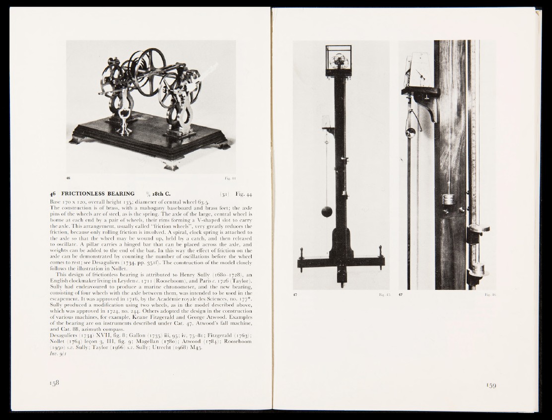
46 FRICTIONLESS BEARING % 18th C. M31) Fig. 44
Base 170 x 120, overall height 135; diameter of central wheel 63.5.
The construction is of brass, with a mahogany baseboard and brass feet ; the axle
pins of the wheels are of steel, as is the spring. The axle of the large, central wheel is
borne at each end by a pair of wheels, their rims forming a V-shaped slot to carry
the axle. This arrangement, usually called “ friction wheels” , very greatly reduces the
friction, because only rolling friction is involved. A spiral, clock spring is attached to
the axle so that the wheel may be wound up, held by a catch, and then released
to oscillate. A pillar carries a hinged bar that can be placed across the axle, and
weights can be added to the end of the bar. In this way the effect of friction on the
axle can be demonstrated by counting the number of oscillations before the wheel
comes to rest; see Desaguliers (1734, pp. 35 if). The Construction of the model closely
follows the illustration in Nollet.
This design of frictionless bearing ifsjattributed to Henry Sully (1680—1728), an
English clockmaker living in Leyden c. 1711 (Rooseboom), and Paris c. 1726 (Taylor') ,
Sully had endeavoured to produce a marine chronometer, and the new bearing,
consisting of four wheels with the axle between them, was intended to be used in the
escapement. It was approved in 1716, by the Académie royale des Sciences, no. ijÊ*.
Sully produced a modification using two wheels, as in the model described above,
which was approved in 1724, no. 244. Others adopted the design in the construction
of various machines, for example, Keane Fitzgerald and George Atwood. Examples
of the bearing are on instruments described under Cat. 47, Atwood’s fall machine,
and Cat. 88, azimuth compass.
Desaguliers (1734) XVII, fig. 8; Gallon (1735) iii, 95; iv, 75-81 ; Fitzgerald (1763B
Nollet (1764) leçon 3, III, fig. 9; Magellan (1780); Atwood (1784JI Rooseboom
(1950) s.v. Sully; Taylor (1966) s.v. Sully; Utrecht (1968) M45.
Inv. g/i