i ia SYPHON FOUNTAIN % 18th C. '§ i5 7 p Fig- I24
A tall (450) mahogany tripod supports a domed glass cylinder (320 x 80), with a
brass collar, a long straight copper tube, and a shorter, bent copper tube. Some
water is put into the cylinder when it is inverted. It is then quickly turned the right
way up, with the bent tube in a bowl of water. The water in the cylinder falls down
the long tube and creates a partial vacuum, thus sucking up water from the bowl
and making a fountain in the cylinder.
Desaguliers (1744) XIX, fig. 10.
Inv. 30/7 ( ?)
113 INTERMITTENT FOUNTAIN % 18th C. (15 1 I Fig. 122
A wide (260) brass dish has fixed to the centre a long brass tube, that runs nearly
to the top of a bell-jar (height 220, diameter 145^ This jar sits on a brass disk with
a rim fixed to the vertical tube (overall height 560). Fitted in the rim are six spouts.
There is a small hole in the bottom of the dish and in the vertical tube.
The bell-jar is three-quarters filled with water, when it pours from the spouts into
the dish. Air returns to the jar via the hole in the bottom of the tube. The dish
gradually fills with water, because its hole is of a smaller capacity than the spouts,
blocks the hole in the tube and cuts off the air, so stopping the flow from the
spouts. When the level in the dish lowers, the spouts pour again.
Musschenbroek (176^ LVI, fig. 1; Adams (1794-) B II> fig- 5-
Inv. 2417
114 INTERMITTENT FOUNTAIN % 18th C. J | i 52) FiS- 122
A solid brass base (no) supports a brass tube running into a cylindrical bell-jar
(height 180, diameter 1 |g), which rests on a brass disk with rim and six spouts (overall
height 460), This fountain stands in an appropriate bowl, and functions in the same
manner as that described above, Cat. 113.
115 INTERMITTENT FOUNTAIN % 18th C. 1158I Fig, 122
This is another example of the intermittent fountain, similar in action to Cat. 113;
and 114, but made in glass, with two spouts, on a brass base. Overall height 350,
diameter of base 125, diameter of bulb 88.
Inv. 24/8
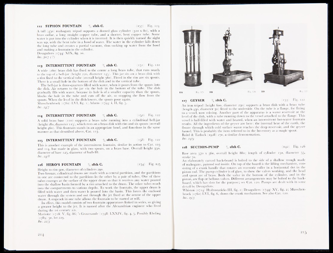
116 HERO’S FOUNTAIN % 18th C. « 1 5 4 ! Fig. 125
Height to rim 900, diameter of cylinders 290.
Two bronze, cylindrical drums are made with a central partition, and the partitions
in one are connected to the partitions in the other by a pair of tubes. One of these
tubes emerges at the surface of the upper drum so that it receives any water poured
into the shallow basin formed by a rim attached to the drum. The other tubes reach
into the compartments to various depths. To work the fountain, the upper drum is
filled with water and then water is poured into the basin. This forces the enclosed
water through the system and out through the jet fixed at the centre of the upper
drum. A stopcock in one tube allows the fountain to be started at will.
In effect, this model consists of two fountain apparatuses linked in series, so giving
a greater height to the jet. It is named after the Alexandrian engineer who lived
during the 1st century a d .
Mariotte (1718) V, fig. 86; ’s Gravesande (1748) LXXIV, fig. 4, 5. Possibly libeling
(1789) 50, lot 229.
Inv. 2213
117 GEYSER % 18th C. ( i53> Fig. 122
An iron tripod (height 600, diameter 230) supports a brass dish with a brass tube
(length 430, diameter 30) fitted to the underside. On the tube is a flange, for fitting
to a vessel, now missing. Another part of the apparatus is a water reservoir at the
level of the dish, with a tube running down to the vessel attached to the flange. This
vessel is half-filled with water and heated, when an intermittent hot-water fountain
results. All the ingredients of the geyser are here: the internal heat of the earth, the
fissure through which cold surface water reaches the deep reservoir, and the geyser
funnel. This is probably the item referred to in the Inventory as a magic spout.
Baird & Tatlock (1928W70, a similar demonstration.
Inv . 24U)
118 SUCTION-PUMP ^ i 8 t h C. (142) Fig. 126
Base area 570 x 360, overall height 880; length of cylinder 150, diameter 55,
stroke 70.
An elaborately carved back-board is bolted to the side of a shallow trough made
of mahogany, painted red inside. On top of the board is the lifting mechanism, consisting
of a crank handle that rotates an eccentric roller in a horizontal slot in the
piston rod. The pump cylinder is of glass, to show the valves working, and the head
and spout are of brass. Both the valve in the bottom of the cylinder, and in the
piston, are flap or bellows valves. Different arrangements may be bolted to the back-
board, which has slots for the purpose; see Cat. 120. Pumps are dealt with in some
detail by Desaguliers.
Whiston (1714) Hydrostaticks III, fig. 2; Desaguliers (1744) XV, fig. 2; Musschenbroek
(1762) LVI, fig. 6, shows the crank mechanism. See also Cat. 120.
Inv. 29I3