170 VACUUM SYPHON c. 1789 (115) Fig. 159
A straight-sided bottle (diameter 43) with brass cap, into which fits one limb of a
doubly bent, capillary-lube syphon (overall height 155). A second, similar bottle for
the other limb is missing.
The bottle is half filled with water and the cap, with the capillary, firmly fitted into
place. It is placed together with a second, open-topped bottle under a bell-jar, which
is then exhausted, causing the water to syphon over.
Inv. 20—21 l j
171 VACUUM FOUNTAIN c. 1789 (611/2) Fig. 137
A glass bottle (overall height 150, diameter 84) has a brass cap into which is fixed
a glass tube reaching nearly to the bottom. A jet orifice is fitted over the tube. The
bottle is partly filled with water and put under a bell-jar. During exhaustion, the
residual air in the bottle expands, and ejects the water as a fountain. This is a simpler
version of the apparatus described under Cat. 172.
Desaguliers (1744) XXV, fig. 19.
Inv. 20—21 lg
172 VACUUM FOUNTAIN c. 1789 (156) Fig. 157
A flat-bottomed, glass flask (overall height 330, diameter 180) is fitted with a brass
collar and a stopcock, with a thread for fitting to a brass disk (diameter 176). Inside
the flask, a tube fixed in the cap runs nearly to the bottom. A bell-jar is put on the
disk, with the stopcock removed from the flask and attached to an air-pump, and
exhausted. It is then transferred to the flask, which is half-filled with water. On opening
the stopcock a fountain is produced.
Desaguliers (1744) XXV, fig. 15.
Inv. 20—21/10
173 AIR PRESSURE FOUNTAIN 1790 (155) Fig. 160
Byjan Paauw, Leyden
This brass cylinder (height 300, diameter 100) is fitted with a long, internal tube, a
stopcock and a jet nozzle (length 100, making overall height 490). It is part-filled
with water and then air is pumped in by a pressure syringe (Cat. 144). When the
nozzle replaces the syringe and the stopcock is turned, a water jet results. The fountain
can also be obtained without pumping up the cylinder. It can be fitted under an
exhausted bell-jar, as described under Cat. 172.
Abr ass pressure fountain, with six jets and a syringe, were bought for f 18 front Jan
Paauw of Leyden on 21 September, 1790 (MV).
’s Gravesande (1748) LX XL fig. 4, pressure; fig. 3, evacuated.
Inv. 22/2
174 AIR PRESSURE FOUNTAIN % 18th C. (141) Fig. 157
A large brass cylinder (height 500, diameter 110), with a splayed base and a projecting
rim at the top, is fitted with a long internal tube, a stopcock and thread to engage
a pressure syringe (Cat. 145), and to attach a jet nozzle (length 260, making overall
height 855). The cylinder is part-filled with water and pumped up. The nozzle is then
fitted, and on turning the stopcock a fountain rises. An alternative mode of use is with
a tall, evacuated bell-jar, which causes the water to be sucked up into a jet within the
bell-jar; see Cat. 172. This fountain is a larger version of that described above
(Cat. 173).
Whiston (1714) Pneumaticks V. fig. 8, “ Jet d’Eaus” ; ’s Gravesande (1748) LXXI,
fig. 4, pressure; fig. 3, evacuated.
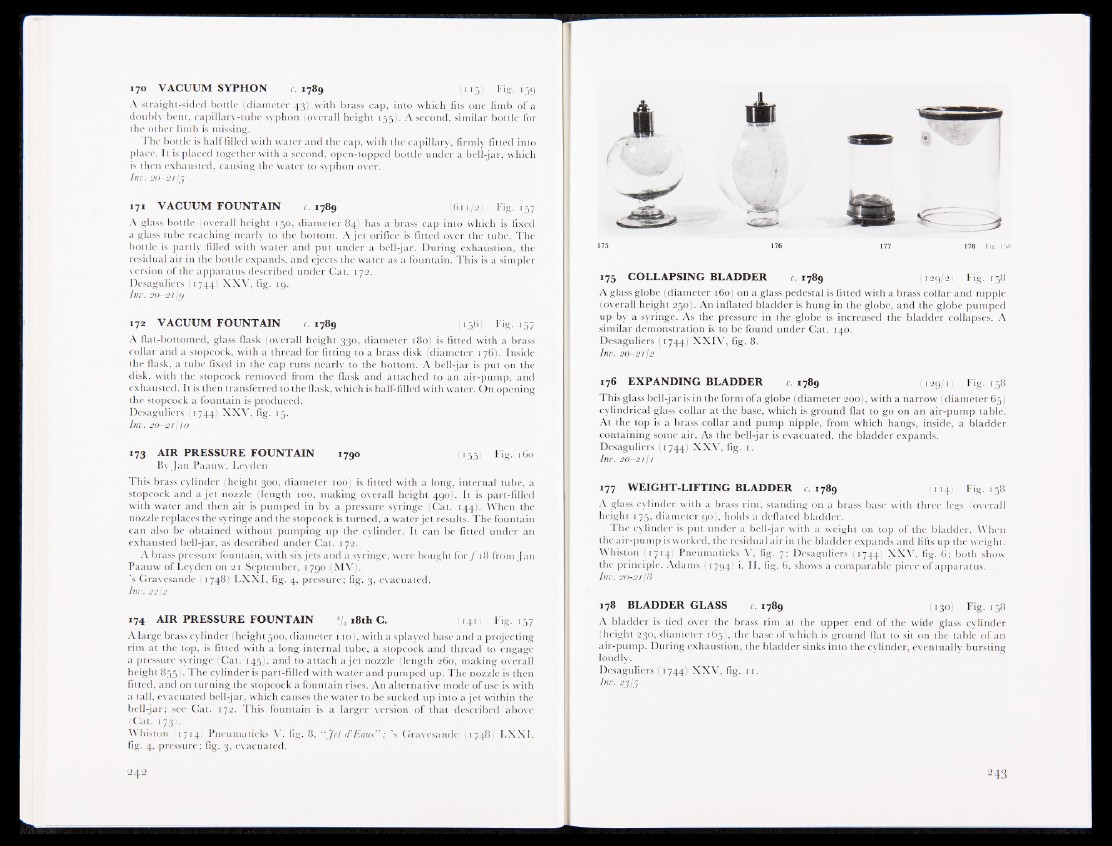
175 176 177 178 l'ig. 158
175 COLLAPSING BLADDER c 1789 (129/2) Fig. 158
A glass globe (diameter 160) on a glass pedestal is fitted with a brass collar and nipple
(overall height 25®J|. An inflated bladder is hung in the globe, and the globe pumped
up by a syringe. As the pressure in the globe is increased the bladder collapses. A
similar demonstration is to be found under Cat. 140.
Desaguliers (1744) XXIV, fig. 8.
Inv. 20—21/2
176 EXPANDING BLADDER c. 1789 (129/1) Fig. 158
This glass bell-jar is in the form ofa globe (diameter 200), with a narrow (diameter 65)
cylindrical glass collar at the base, which is ground flat to go on an air-pump table.
At the top is a brass collar and pump nipple, from which hangs, inside, a bladder
containing some air. As the bell-jar is evacuated, the bladder expands.
Desaguliers (1744) XXV, fig. 1.
Inv. 20—2111
177 WEIGHT-LIFTING BLADDER c. 1789 (114) Fig. 158
A glass cylinder with a brass rim, standing on a brass base with three legs (overall
height 175, diameter 90), holds a deflated bladder.
The cylinder is put under a bell-jar with a weight on top of the bladder. When
the air-pump is worked, the residual air in the bladder expands and lifts up the weight.
Whiston (1714) Pneumaticks V, fig. 7; Desaguliers (1744) XXV, fig. 6; both show
the principle. Adams (1794) i, II, fig. 6, shows a comparable piece of apparatus.
Inv. 20-2118
178 BLADDER GLASS c. 1789 (130) Fig. 158
A bladder is tied over the brass rim at the upper end of the wide glass cylinder
(height 230, diameter 165), the base of which is ground flat to sit on the table of an
air-pump. During exhaustion, the bladder sinks into the cylinder, eventually bursting
loudly.
Desaguliers (1744) XXV, fig. 11.
Inv. 23/5