n g FORCE-PUMP 3u 18th C. (149P Fig. 127
By Jacobus Kley, Rotterdam
Base area 410 x 350, overall height 730'; length of cylinder 200, diameter 39, stroke §0.
A carved and pierced, mahogany back-board is fixed to a mahogany trough, and
the top carries a housing for the lifting mechanism. The pump cylinder and reservoir
are of brass. The rotary motion of the crank is converted to recipr|||ating motion by
a double rack at the top of IJje piston rod, which%;>#jjgaged by a wheel that has
teeth cut for one-third of its circumference only.. The invention of this mechanism
was claimed by Auger in 1721, and was recorded under no. 22,3, by the AKademie
Royale des Sciences. This mechanism is illustrated in Musschenbroek, and Jacobus
Kley (1716—1791) was his instrument-maker. According to the Inventory, Kley was
the maker of this pump.
This pump has a double action. First it sucks the water into the cylinder, but instead
of lifting it to a spout, it pushes it into a side reservoir. Air trapped in this reservoir
helps to expel water on the upstroke, so the device can be.adapted for use as a fire
extinguisher.
Whiston (1714) Hydrostaticks III, fig. 3; Galkfi Ji 735) iv, 19; Desaguliers (1744)
XV, fig. 4; Musschenbroek ; 1 762) LVI, fig;.'Jy
Inv. *2g/i
120 WATER-PUMP VALVES &c % 18th C. (880)' Fig. 128
A collection of valves, tubes and nozzles, mostly for use with the pump described
under Cat. 118. Included are parts for a lifting-pump, and a force-pump side tube
and reservoir, corresponding to Desaguliers (1744) XV, fig. 1 and 5 respectively.
On 20 November, 1788, Van Marum attended the auction sale of the effects of
Steenstra, and there bought what he called pump apparatus for ƒ 161. This is before
he had an air-pump, so it may be water-pump apparatus that is being referred to.
Inv. 2g/j
121
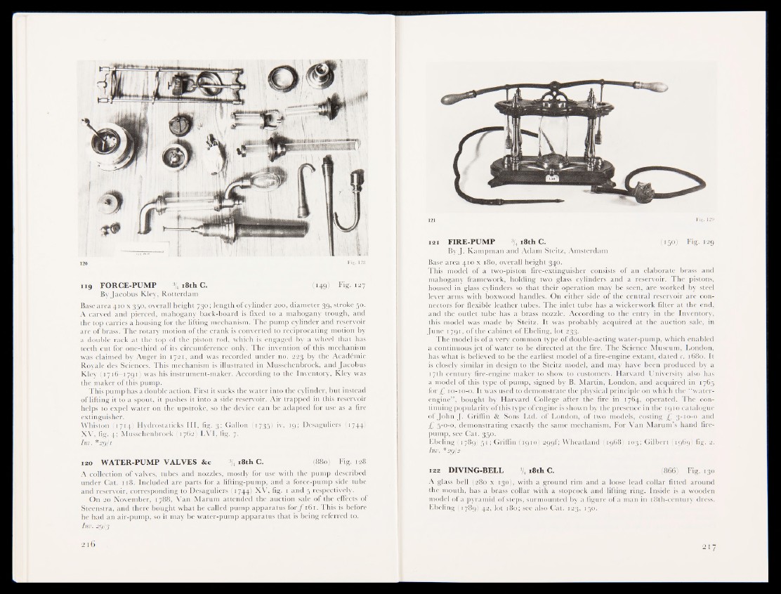
121 FIRE-PUMP % 18th C. (150) Fig. 129
By J. Kampman and Adam Steitz, Amsterdam
Base area 410 x 180, overall height 340.
This model of a two-piston fire-extinguisher consists of an elaborate brass and
mahogany framework, holding two glass cylinders and a reservoir. The pistons,
housed in glass cylinders so that their operation may be seen, are worked by steel
lever arms with boxwood handles. On either side of the central reservoir are connectors
for flexible leather tubes. The inlet tube has a wickerwork filter at the end,
and the outlet tube has a brass nozzle. According to the entry in the Inventory,
this model was made by Steitz. It was probably acquired at the auction sale, in
June 1791, of the cabinet of Ebeling, lot 23j|k"-i
The model is of a very common type of double-acting water-pump, which enabled
a continuous jet of water to be directed at the fire. The Science Museum, London,
has what is believed to be the earliest model of a fire-engine extant, dated c. 1680. It
is cpfeely similar in design to the Steitz model, and may have been produced by a
1 Bh'Century fire-engige maker to show to customers. Harvard University also has
a model of this type of pump, signed by B. Martin, London, and acquired in 1765
for £ 10-10-0. It was used to demonstrate the physical principle on which the “water-
engine” , bought by Harvard College after the fire in 1764, operated. The continuing
popularity of this type of engine is shown by the presence in the 1910 catalogue
of John J. Griffin & Sons Ltd. of London, of two models, costing -£ 3-10-0 and
£ 5-0-0, demonstrating exactly the same mechanism. For Van Marum’s hand fire-
pump, see Cat. 350.
Ebeling (1789) 51; Griffin (1910) 299L Wheatland (1968) 103; Gilbert (1969) fig. 2.
Inv. *2g':2
122 DIVING-BELL \ 18th C. (866) Fig. 130
A glass bell (280 x 130), with a ground rim and a loose lead collar fitted around
the mouth, has a brass collar with a stopcock and lifting ring. Inside is a wooden
model of a pyramid of steps, surmounted by a figure of a man in 18th-century dress.
Ebeling (1789) 42, lot 180; see also Cat. 123, 150.