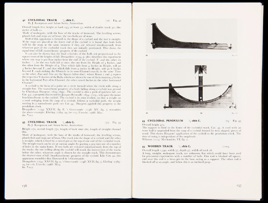
42 CYCLOIDAL TRACK % 18th C. (72) Fig. 42
By J. Kampman and Adam Steitz, Amsterdam
Overall length 810, height at back 245, at front 57, width of double track 50; diameter
of balls 21.
Made of mahogany, with the base of the tracks of boxwood. The levelling screws,
plumb-bob and stops are of brass; the two balls are of stone.
Half of this apparatus is formed in the shape of a cycloid and the rest is straight.
If the stops are placed at the lower end of the cycloid it is found that both balls
will hit the stops at the same moment if they are released simultaneously from
whatever part of the cycloidal track they are initially positioned. This shows the
equal time of fall (tautochrone) property of the cycloid.
It can also be shown that the final velocities of the balls ar^ proportional to the
square roots of the heights of fall. Desaguliers (1734, p. 380) describes this experiment
where one stop is put four inches from the end of the cycloid (F) and the other six
inches: “ ...let the two balls fall at once, the one from the Height of 4 Inches, and
the other from the Height of 9. That which falls from 4 Inches in Height, will go
4 Inches beyond F; and that which falls from 9 inches in Height, will go 6 Inches
beyond F, each striking the Obstacle in its own Channel exactly in the same Time
as the other. Four and Nine are the Spaces fallen thro’, whose Roots 2 and 3 express
the respective Velocities of the Balls, which are shewn by one of them running 4 Inches
in the horizontal Part of its Channel, the other runs 6 Inches in the other horizontal
Channel” .
A cycloid is the locus of a point on a circle formed when the circle rolls along a
straight line. The tautochrone property of a body falling along a cycloid was proved
by Christiaan Huygens (1629-1695],,('The cycloid is also a path of quickest till |see
Cat. 43), a property discovered by Jacques Bernoulli (1654-1705), who gave the name
brachistochrone to the cycloid. The cycloid is its own evolute, so that a weight on
a cord swinging from the cusp of a cycloid, follows a cycloidal path, the weight
moving in a tautochrone path (see Cat 44), Huygens applied this property to the
pendulum clock.
Desaguliers (1734) XXVII, fig. 8; ’s Gravesande (1748) XV, fig. 7, resembles
the above example; Ebeling (1789) 29, lot 115; Utrecht (1968) M21.
Inv. *10/1
43 CYCLOIDAL TRACK % 18th C. (73) Fig. 43
ByJ. Kampman and Adam Steitz, Amsterdam
Height 270, overall length 770, length of back strut 260, length of straight channel
860.
Made of mahogany, with the base of the tracks of boxwood1; the levelling screws,
plumb-bob and stops are of brass. One track is in the shape of a cycloid and the other
is straight, which is fixed by a swivel-pin at the top of one end of the cycloidal track.
The straight track can be set at various angles by putting a peg into one of a number
of holes in the main frame. If two balls are released simultaneously from the top of
the tracks, the one rolling along the cycloid will reach the intersection of the tracks
before the other, whatever angle is chosen for the straight track. This demonstrates
the shortest time of fall (brachistochrone) property of the cycloid. Like Cat. 42, this
apparatus resembles that illustrated in ’s Gravesande.
Desaguliers (1734) XXVII, fig. 9; ’s Gravesandeji748) XVII, fig. 3; Kbeling (1789)
2g, lot 116; Utrecht (1968) M23.
Inv. *10/2
42
43 44 Fig. 43
44 CYCLOIDAL PENDULUM % l8th C. (74) Fig. 43
Overall height 475.
The support is fixed to the frame of the cycloidal track, Cat. 43. A cord with an
ivory ball is suspended from the cusp of a cycloid formed by two, shaped, pieces of
wood. This shows Huygens’ application of the cycloid to the pendulum clock. The
time of swing is independent of the amplitude.
Whiston (1714) Mechanicks, VI, fig. 2.
45 WOODEN TRACK 3/4 18th C. (1104)
Overall length 1,340, width 37, depth 47; width of track 26.
A long, straight, mahogany track, use unknown, but which could have been used
for percussion experiments with a number of balls. One end is blocked off square,
and near this end is a brass pin in the base acting as a support. The-other end is
blocked off at an angle, and below this is an inclined prop.