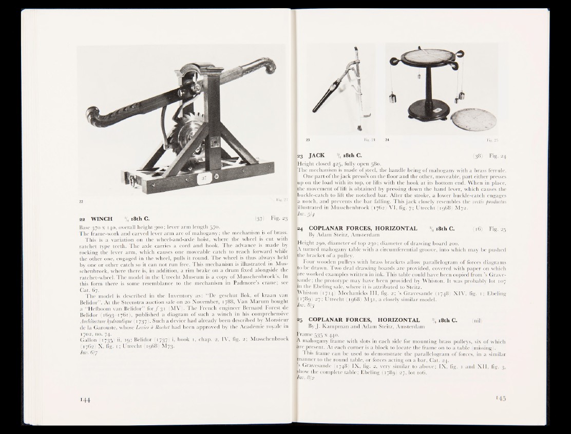
22 WINCH % 18th C. ;ir(«37) Fig- 23
Base 370 x 140, overall height 300; lever arm length l'p».
The frame-work and carved lever arm are of mahogany; the mechanism islqf brass*.
This is a variation on the wheel-and-axle hoist, where the wheel is cut with
ratchet type teeth. The axle carries a cord and hook. The advance is made by
rocking the lever arm, which causes one moveable catch to reach forward while
the other one, engaged in the wheel, pulls it round. The wheel is: thus always held
by one or other catch so it can not run free. This mechanism is illustrated in Mus-
schenbroek, where there is, in addition, a rim brake on a drum fixed alongside the
ratchet-wheel. The model in the Utrecht Museum is a copy of Musschenbroek's. In
this form there is some resemblance to the mechanism in Padmorefi crane; see
Cat. 67.
The model is described in the Inventory as: “De geschut Bok, of kraan van
Belidor” . At the Steenstra auction sale on 20 November, t 788. Van Marum bought
a “ Hefboom van Belidor” for ƒ 31 (MV;. The French engineer Bernard Forest de
Belidor (1693—1761), published diagram of such a winch in his comprehensive
Architecture hydraulique (17375- Such a device had already been described by Monsieur
de la Garouste, whose Levier à Rochet had been approved by the Académie royale in
1702, no. 74.
Gallon (1735) ii, 19; Belidor i, book 1, chap. 2, IV, fig, 2; Musschenbroek
(1762) X, fig. 1 ; Utrecht (1968) M73.
Inv.6l7
144
23 JACK % 18th C. (38) Fig. 24
[Height closed 425, fully open 580,
[The mechanism is made of steel, the handle being of mahogany with a brass ferrule.
I One part of the jack press® on the floor and the other, moveable, part either presses
lip on 1 he load with its top, or lifts with the hook at its bottom end. When in place,
l:he moyement' df lift is obtained by pressing down the hand lever, which causes the
[buckle-catch to lift the notched bar. After the stroke, a lower buckle-catch engages
la notch, and prevents the bar falling. This jack closely resembles the vectis productus
«illustrated in Musschenbroek (1762) VI, fig, 7; Utrecht (1968) M72.
Vm- 5:4
[24 COPLANAR FORCES, HORIZONTAL % 18th C. (16) Fig. 25
By Adam Steitz, Amsterdam
[Height 290, diameter of top 230 ; diameter of drawing board goo.
|A turned mahogany table with a circumferential groove, into which may be pushed
■ the bracket bf a pulley.
I Four wooden pulleys with brass brackets allow parallelogram of forces diagrams
to be drawn. Two deal drawing boards are provided, covered with paper on which
fere worked examples written in ink. This table could have been copied from’s Grave-
ftandSthe prototype may have been provided by Whiston. It was probably lot 107
In the Ebeling sale, where it is attributed to Steitz.
wVhisfsn (1714I Mechanicks III, fig. 2; ’s Gravesande (1748) XIV, fig. 1; Ebeling
B1789) 27; Utrecht (1968) M3r, a closely similar model.
Wnv. 8/3
25 COPLANAR FORCES, HORIZONTAL % 18th C. (nil)
By J. Kampman and Adam Steitz, Amsterdam
frame 535 x 440.
A mahogany frame with slots in each side for mounting brass pulleys, six of which
are present. At each porner is a block to locate the frame on to a table (missing). ’
I This frame can be used to demonstrate the parallelogram of forces, in a similar
frnanner to the jfpijjnd table, or forces acting on a bar, Cat. 24.
Is Gravesande (1748) IX, fig. 2, very similar to above; IX, fig. 1 and XII, fig. 3,
Bhpw the complete table; Ebeling (1789) 27, lot 106.
unv. 8f:2
MS