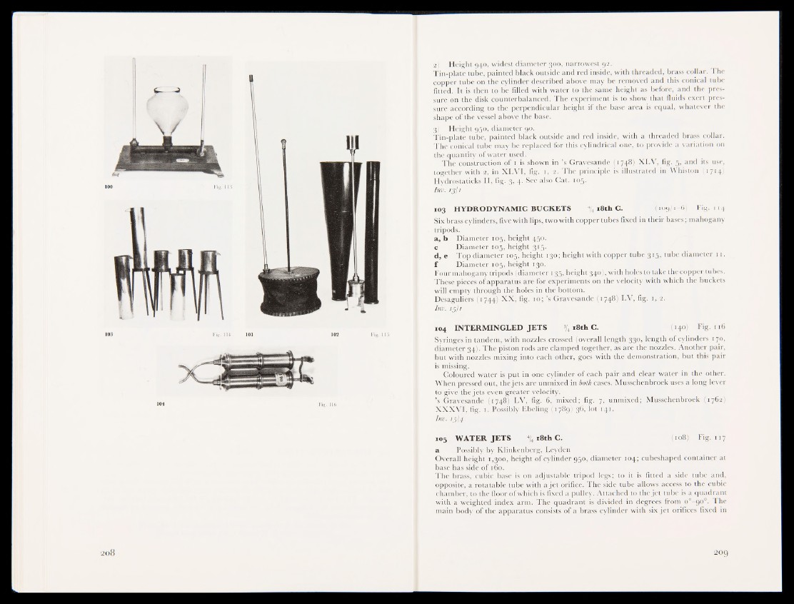
2) Height 940, widest diameter 300, narrowest 92.
Tin-plate tube, painted black outside and red inside, with threaded, brass collar. The
copper tube on the cylinder described above may be removed and this conical tube
fitted. It is then to be filled with water to the same height as before, and the pressure
on the disk counterbalanced. The experiment is to show that fluids exert pressure
according to the perpendicular height if the base area is equal, whatever the
shape of the vessel above the base.
i f Height 930, diameler 90.
Tin-plate tube, painted black outside and red inside, with a threaded brass collar.
The conical tube may be replaced for this cylindrical one, to provide a variation on
the quantity of water used.
The construction of 1 is shown in ’s Gravesande (1748) XLV, fig. 5, and its use,
together with 2, in XLVI, fig. 1, 2. The principle is illustrated in Whiston (1714)
Hydrostaticks II, fig. 3, 4. See also Cat. 105.
Inv. 13:1
103 HYDRODYNAMIC BUCKETS % 18th C. (109/1-6) Fig. 114
Six brass cylinders, five with lips, two with copper tubes fixed in their bases; mahogany
tripods.
a , b Diameter 105, height 450.
c Diameter 105, height 315.
d, e Top diameter 105-, height 130; height with copper tube 315, tube diameter 11.
f Diameter 105, height 130,
Four mahogany tripods (diameter 135» height 340), with holes to take the copper tubes.
These pieces of apparatus are-for experiments on the velocity with which the buckets
will empty through the^ioles in the bottom.
Desaguliers f|i744) XX, fig. 10; ’s Gravesande (1748) LV, fig. 1, 2.
Inv. | jp
104 INTERMINGLED JETS \ 18th C. (140) Fig. 116
Syringes in tandem, with nozzles crossed (overall length 330, length of cylinders 170,
diameter 34). The piston rods are clamped together, as are the nozzles. Another pair,
but with no'zzles mixing into each other, goes with the demonstration, but this pair
is missing.
Coloured water is put in one cylinder of each pair and clear water in the other.
When pressed out, the jetj^kre unmixed in both cases. Musschenbroek uses a long lever
to give the jets« even greater velocity.
’s Gravesande (#748) LV, fig. 6, mixed; fig. % unmixed; Musschenbroek (1762)
XXXVI, fig. 1. Possibly Finding (1 769) 36, lot 141.
Inv. 15I4
105 WATER JETS % 18th C. (108) Fig. 117
a Possibly by Klinkenberg, Leyden
Overall height 1,300, height of cylinder 950, diameter 104; cubeshaped container at
base has side of 160.
The brass, culUc b|f|e is on adjustable tripod legs; to it is fitted a side tube and,
opposite, a rotatable tube with a jet orifice. The side tube allows access to the cubic
chamber, to the floor of which is fixed a pulley. Attached to the jet tube is a quadrant
with a weighted index arm. The quadrant is divided in degrees from o°-90°. The
main body of the apparatus consists of a brass cylinder with six jet orifices fixed in