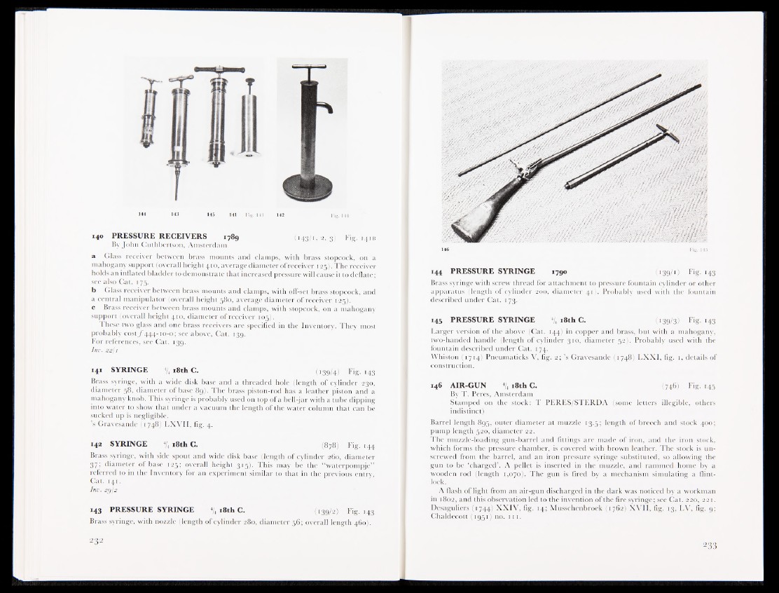
140 PRESSURE RECEIVERS 1789 (143/1,2,3) Fig. 141 b
By John Outhbcrlson, Amsterdam
a Glass receiver between brass mounts and clamps, with brass stopcock, on a
mahogany support (overall height 410, average diameter of receiver 1 25);, The receiver
holds an inflated bladder to demonstrate that increased pressure will cause it to deflate;
see also Cat. 175.
b Glass receiver between brass mounts and clamps, with off-set brass stopcock, and
a central manipulator (overall height 580, average diameter of receiver 125J.., •
c Brass receiver between brass mounts and clamps, with stopcock, on a mahogany
support (overall height 410, diameter of receiver 105).
These two glass and one brass receivers are specified in the Inventory. They most
probably cost ƒ 444-10-0; see above, Cat. 139.
For references, see Cat. 139.
Inv. 22/1
141 SYRINGE 4/4 18th C. (139/4) Fig- 143
Brass syringe, with a wide disk base and a threaded hole (length of cylinder 230,
diameter 58, diameter of base 89). The brass piston-rod has a leather piston and a
mahogany knob. This syringe is probably used on top of a bell-jar with a tube dipping
into water to show that under a vacuum the length of the water column that can be
sucked up is negligible.
’s Gravesande (1748) LXVII, fig. 4.
142 SYRINGE 4/4 18th C. (878) Fig. 144
Brass syringe, with side spout and wide disk base (length of cylinder 260, diameter
37! diameter of base 125; overall height 315)- This may be the “waterpompje”
referred to in the Inventory for an experiment similar to that in the previous entry,
Cat. 141.
Inv. 2gj2
143 PRESSURE SYRINGE 4/4 18th C. (139/2) Fig. 143
Brass syringe, with nozzle (length of cylinder 280, diameter 56; overall length 460).
146 Fig. 145
144 PRESSURE SYRINGE 1790 (139/1) Fig. 143
Brass syringe with screw thread for attachment to pressure fountain cylinder or other
apparatus (length of cylinder 200, diameter 41). Probably used with the fountain
described under Cat. 173.
145 PRESSURE SYRINGE 4/4 18th C. (139/3) Fig. 143
Larger version of the above (Cat. 144) in copper and brass, but with a mahogany,
two-handed handle (length of cylinder 310, diameter 52). Probably used with the
fountain described under Cat. 174.
Whiston (1714) Pneumaticks V, fig. 2; ’s Gravesande (1748) LXXI, fig. 1, details of
construction.
146 AIR-GUN 4/4 i8thC. (746) Fig. 145
By T. Peres, Amsterdam
Stamped on the stock: T PERES/STERDA (some letters illegible, others
indistinct)
Barrel length 895, outer diameter at muzzle 13.5; length of breech and stock 400;
pump length 520, diameter 22.
The muzzle-loading gun-barrel and fittings are made of iron, and the iron stock,
which forms the pressure chamber, is covered with brown leather. The stock is unscrewed
from the barrel, and an iron pressure syringe substituted, so allowing the
gun to be ‘charged’. A pellet is inserted in the muzzle, and rammed home by a
wooden rod (length 1,070). The gun is fired by a mechanism simulating a flintlock.
A flash of light from an air-gun discharged in the dark was noticed by a workman
in 1802, and this observation led to the invention of the fire syringe; see Cal. 220, 22 1.
Desaguliers (1744) XXIV, fig. 14; Musschenbroek (1762) XVII, fig. 13, LV, fig. 9;
Chaldecott (1951) no. 111.