89 Fig. 9 4 89 F« ' 95
89 AZIMUTH COMPASS 1790 (4 6&) Flffi 94= 95
By Kenneth McCulldch, London
Signed on the compass card: MCCULLOCH, Compass-maker to his Royal
Highness' PRINCE WILLIAM HENRY, N<? 38, MINORIES.LONDON.
PATENT; on the bottom of the compass case: K. M?CULLOCH PATENT;
on the sighting bar: MCCULLOCH PATENT
Base area of mahogany box 375 x 370; diameter of compass bowl 2*§, height 102,
diameter of compass card 200. .
Mahogany box, lid missing, with brass pivot screwed to the bottom supporting the
brass compass bowl with glass top. Four pieces of wood swivel from each corner of
the box to hold the compass firmly when not in use. A pair of wooden brackets hold
the sighting bar until required.
This design of mariner’s compass was patented on 12 August, 1788, no. 1663, by
Kenneth McCulloch, and in the following year he published a Description The cost
of the compass varied between nine and twelve guineas. The noveltpof McCulloch’s
compass is in the mounting, which avoids the use of gimbaliiiThe base of the compass
bowl is made conical, with the apex protruding half-way into the case. The whole is
balanced on a pivot with a spherical tip locating in the apex of the base. At the side
of the bowl is a pair of slotted brackets to prevent the compels from migrating on it#
axis. At the bottom of the conical base is lead weighting to bring thercentrc of gwivity
well below the point of support. The compass card is pivoted on the apex of the base,
so the points of support of the bowl and the card are as close as possible. In the
steering compass version, the pair of side stays are screwed to the wooden base Amt
in the azimuth compass they are connected, and swivel when necessary about the
pivot Above the glass top of the compass may be attached a brass bar with slit sights
in the vanes (length 100) and a cord stretching from their tips. Sliding on the sight
vanes is a dark red glass (diameter 5) and a magnifying glass (diameter 1 igSWhen a
sighting has been made, or the shadow of the cord aligned with the fiducial line on
the bar, the compass card is stopped from rotating by pressing on a rod protruding
from the side of the case. The reading is then taken by viewing the vernier fixed to
the wall of the case by means of the inclinable lens (diameter 22) attached to the bar.
The compass card is marked with the half-points of the compass|j64ths of a circle),
and the rim is divided in half degrees, inscribed from north o»i8o°-o°. The vernier
is a strip of brass inscribed with diagonals.
Van Marum records that when in London during July 1790, he bought from
Dollond: “Een Zee Compas van Cullock ■ £ 9-9-0’l M ^ Dollond was, apparently,
acting as an agent for McCulloch. For a note on the use of the azimuth compass, and
for references, see Cat. 88.
McCulloch (1789).
Inv. 76/3
J94
90
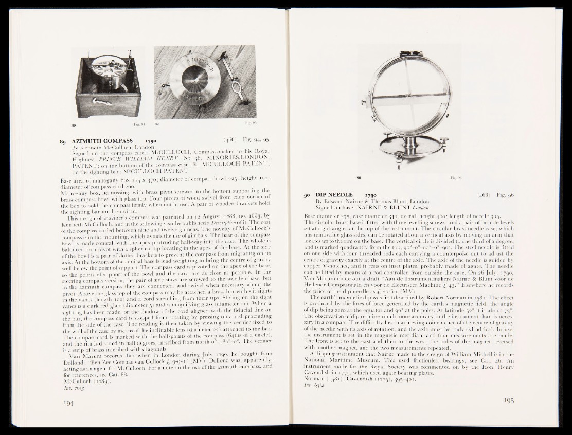
90 DIP NEEDLE 1790 (468) Fig. 96
By Edward Nairne & Thomas Blunt, London
Signed on base: NAIRNE & BLUNT London
Base diameter 275, case diameter 340, overall height 460; length of needle 305.
The circular brass base is fitted with three levelling screws, and a pair of bubble levels
set at right angles at the top of the instrument. The circular brass needle case, which
has removable glaf§ sides, can be rotated about a vertical axis by moving an arm that
locates up to the rim on the base. The vertical circle is divided to one third of a degree,
and is marked quadrantly from the top, 900—o°^900-o°—90°. The steel needle is fitted
on one side with four threaded rods each carrying a counterpoise nut to adjust the
centre of gravity exactly at the centre of the axle. The axle of the needle is guided by
copper V-notches, and it rests on inset plates, probably made of agate. The needle
can be lifted by means of a rod controlled from outside the case. On 26 July, 1790,
Van Marum made out a draft “Aan de Instrumentmakers Nairne & Blunt voor de
Hellende Compasnaald en voor de Electriseer Machine £ 43.” Elsewhere he records
the price of the dip needle as ■ £ 27-6-0 (MV).
The earth’s magnetic dip was first described by Robert Norman in 1581. The effect
is produced by the lines of force generated by the earth’s magnetic field, the angle
of dip being zero at the equator and 90° at the poles. At latitude 520 it is about 73°.
The observation of dip requires much more accuracy in the instrument than is necessary
in a compass. The difficulty lies in achieving coincidence of the centre of gravity
of the needle with its axis of rotation, and the axle must be truly cylindrical. In use,
the instrument is set in the magnetic meridian, and four measurements are made.
The front is set to the east and then to the west, the poles of the magnet reversed
with another magnet, and the two measurements repeated.
A dipping instrument that Nairne made to the design of William Michell is in the
National Maritime Museum. This used frictionless bearings; see Cat. 46. An
instrument made for the Royal Society was commented on by the Hon. Henry
Cavendish in 1775, which used agate bearing plates.
Norman ( 1 5 8 1 Cavendish (1775), 395-401.
Inv. 63/2
195