This is an example of a worm-drive applied to a whetf-ÿncbaxle. The worm-screw
(schroef zonder eind) engages a cog-wheel whose teeth are cut Square. A cord can be
attached to the barrel lor hoisting heavy weights. This machine is described in the
Inventory as : “ Steenwinder genaamd” , and the description closely follows the libeling
catalogue, lot 77, where the maker of the metal parts is given as Wier, and of the
mahogany parts as Kampman.
Ebeling (1789/22; Utrecht (1968) M86.
Inv. 5/9
19 WORM-DRIVE % 18th C. j Fig. 20
By Jacobus Kley, Rotterdam
Signed on dial plate: J. Kleij Fecit. ROTTERDAM
Base 180 x 170, overall height 280 - top pulley diameter 237.
Made of brass, with a steel worm and shaft, mahogany base, cord drum and pulley.
This model is a larger, more elaborate version of ( la 1. 16. Here the steel worm
on a steel shaft engages a brass gear-wheel whose teeth are cut square, on the axle of
which is a pinion that drives another large wheel on the lower axle. On this axle a
cord can be attached to lift a heavy weight. The drive is supplied by a small weight
on a cord attached to the large wooden pulley on the shaft of the worm-screw. The
bracket to carry the small pulley over which the driving cord must hang is missing,
but two screw holes in the frame show its point of attachment. The upper axle carries
a cord-winding drum fitted with a ratchet. Both upper and lower axles turn clock
hands across the faces of two dial plates calibrated from o to 10 units (marked in
Roman numerals), each unit subdivided into eighths. One unit on the upper d ia l«
equivalent to a quarter of a unit on the lower. Seven revolutions of the worm shaft
equal one unit on the upper dial. The model is probably to be identified with the
wheel-work by Kley that Van Marum bought for ƒ 24 at the Steenstra sale on
20 November, 1788 (MV).
This model closely resembles that illustrated by Petrus van Musschenbroek
(1692-1761), and Jacobus Kley (1716-1791) was one of his instrument makers. A
very similar machine in the Utrecht Museum was bought by the Academy in 175?
from Kley. The form of the wooden feet of the baseboard is characteristic of many
in thcTeylers Museum, atjd as this machine was bought at an auction sale, it is
possible that it was subsequently mounted on a stand, perhaps by Paauw.
WhistonHi7i« Mechanicks IV, fig. 4, 8; Musschenbroek (1762) IX, fig. 7;
ltreehf (1968; M87.
Inv. 5/7
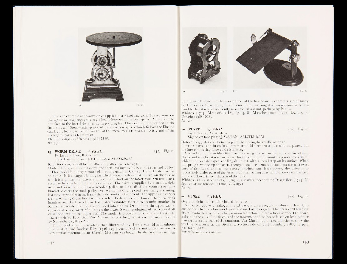
20 FUSEE -^ iS thC . (32) Fig. 21
ByJ. Waten, Amsterdam
Signed on face plate: J. WATEN, AMSTELDAM
Plates; 78 x gg; distance between plates 30; spring-barrel diameter 30.
A spring-barrel and brass fusee screw are held between a pair of brass plates, but
the interconnecting fusee chain is missing.
Waten has not been identified, so the dating is not conclusive. In spring-driven
Hocks and watches it was customary for the spring to transmit its power via a fusee,
which is a conical-shaped winding drum cut with a spiral step on its surface. When
the spring is w«nd up and at its strongest, the drive-chain operates on the narrowest
part ;§if the fusee, and as the spring unwinds and loses power, the drive is to
[successively wider parts of the fusee, thus maintaining constant the power transmitted
to the clock-work from the axis of the fusee.
Whiston (1714) Mechanicks, V, fig. 4, a similar mechanism; Desaguliers (1734) X,
pig. 12; Musschenbroek j l 762) VII, fig. 1.
Urn. 6/1
lai FUSEE % 18th C. (30) Fig. 22
(Overall hi fight 140; moving board 140 x 100.
I Supported above a mahogany, oval base, is a rectangular mahogany board, to
lone side of which is a boxwood quadrant marked in degrees. The brass cord-winding
[drum, controlled by the ratchet, is mounted below the brass fusee screw. The board
bs fixed to the axis of the fusee, and the movement of the board is shown by a pointer
[passing across the scale of the quadrant. Van Marum purchased a device to show the
»working of a fusee at the Steenstra auction sale on 20 November, 1788; he paid
l/To for it (MV).
[For references see Cat. 20.