The inclined plane demonstrates the forces required to move a mass borne on
rollers along slopes of various inclinations. In this model, variation in the direction
of the application of the force can be made by using a separately mounted pulley.
A semicircular, and a triangular, angle-setting plate serve to set the position of the
bar and the cord respectively.
The semicircular plate (radius yo) is inscribed with lines marked, 6, 8, io, t2, 14?
16. The straight edge is put to the underside of the adjustable arm, and a plumbline
(missing) allows the angle of inclination to be made to correspond to one of the
inscribed lines. The sjiding cylinder, which is fitted with small rollers on the inside,
is considered to weigh 16 ounces, and will be just balanced at the selected angle by
a weight of 6, 8, to etc. ounces. For a force of 16 ounces, the arm would be vertical.
The triangular plate (height 118) is inscribed with lines marked 9, 10, r, 11, 16
and is used by setting the shortest edge to the top of the bar and adjusting the bar
so that the 16-ounce line is vertical. By means of a separately mounted pulley, the
cord can be made to act in a direction corresponding to one of the lines, when the
balancing weight is shown by the appropriate number. The line r divides the side
of the triangle into two equal parts. When the cord is below this hneo|he leverage
is on the front roller in the cylinder, and when above the line the leverage is on the
back roller.
This model exactly corresponds to the illustration in ’s Gravesande (1748 Hand it
is intended to demonstrate the forces found in the action of the centrifuge machine,
the sliding cylinder is similar to those in use on that machine made by Steitz (see
Cat. 49).
’s Gravesande (1748) XIII, fig. 5, 6; Ebelmg (1789) 16,Bit 52.
Inv. 4I3
37 TRACTION 3/4 r8th C. Fig - 36
Four-wheeled, brass trolley, axle length 153, track 128, wheel diameter 101, inter
axle distance 210.
Two-wheeled axle and draw-pole of brass, axle length 153, track 130, wheel diameter
50.5, pole length 180.
This representation of a carriage has an interchangeable pair of wheels to
demonstrate the effects of wheel size. According to the Inventory, there should be
two boards to simulate an uneven carriage-way, but these are missing. Desaguliers
devoted considerable space to discussing the design of carriages and the effects of
road surfaces. Whiston used a four-wheeled “Imitation of a Waggon or Coach” with
his inclined plane; see Cat. 35.
Desaguliers (1734) 201-299, XVII, especially fig. ifgEbeling (1789) 28, lot 112:.
Inv. g/2
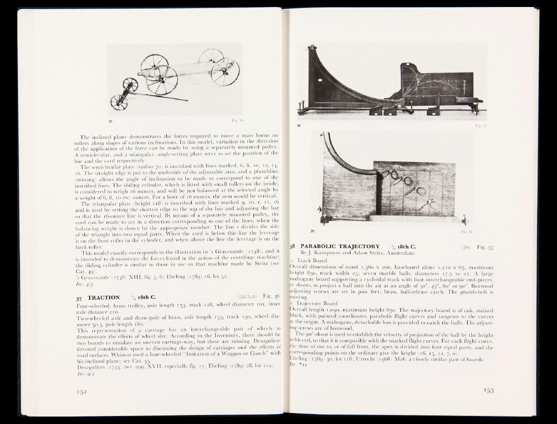
38 PARABOLIC TRAJECTORY % l8th c . (70) Fig. 37
By J. Kampman and Adam Steitz, Amsterdam
H) Track Board
jDverall dimensions of stand 1,360 x 200, baseboard alone 1,210 x 65, maximum
lbeight 850, track width 25; seven marble balls, diameters 17.5 to 21. A large
Imahogany board supportinjla cycloidal track with four interchangeable end-pieces,
Ipr shoots, to project a ball into the air at an angle of 30°, 450, 60° or 90°. Boxwood
adjusting screws are set in paw feet; brass, ball-release catch. The plumb-bob is
trussing.
fc) Trajectory Board
gpverall length 1,090, maximum height 650. The trajectory board is of oak, stained
fclack, with painted coordinates, parabolic flight curves and tangents to the curves
fet the origin. A mahogany, detachable box is provided to catch the balls. The adjusting
screws are of boxwood.
I The go0-shoot is used to establish the velocity of projection of the ball by the height
fechieved, so that it is compatible with the marked flight curves. For each flight curve,
Ithe time dSH.se to, or of fall from, the apex is divided into four equal parts, and the
corresponding points on the ordinate give the height (16, 15, 12, 7, o).
Ebeling (1789) 30, lot 118; Utrecht (1968) M26, a closely similar pair of boards.
Vnv. * u