321 SPINNING INSTRUMENT: Nicholson’s 1790 p i 15 J * Fig. 283, 284
By George Adams, London
Base diameter 107, overall height 158, diameter of spinning disk 58.
The wide, stable base, weighted with a lead ring, supports a brass, bulbous pillar,
through which runs the steel shaft of the spinning disk. Between the pillar and the shaft
are nesting amber cups, both silver-foiled in halves, the upper cup outside and the
lower inside. There is evidence of there having been small attachments, now missing.
This instrument was sent on 17 December, 1790, by Adams along with other goods,
and was listed by him as: “ Mr. Nicholson’s new instrument £ 2-10-0” . It is not,
however, recorded in the Inventory.
Fy.8-
321 I'ig. 284
As this particular invention of William Nicholson has never before been referred
to in the literature, apart from his own Journal, a description of it is given here in
addition to the account of its origin quoted above.
Nicholson started his Journal of Natural Philosophy, Chemistry and the Arts in 1797, and
perhaps because the first issue was difficult to fill, he included a description of his
own instrument, which he had last seen seven years previously. This may explain why
the rotating glass plates in the illustration are flat and not dished, as in reality. Otherwise,
the description fits the instrument in Teyler’s Museum very well. The title of
the paper is: “ Description of an Instrument which renders the Electricity of the
Atmosphere and other weak Charges very perceptible, without the possibility of an
equivocal Result” . The following passage is taken from pages 17—18:
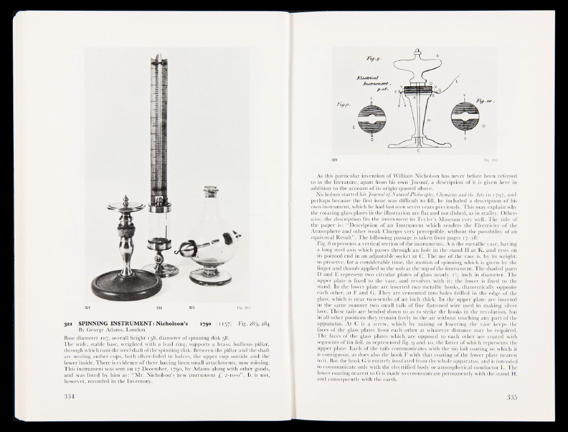
Fig. 8 represents a vertical section of the instruments. A is the metallic vase, having
a long steel axis which passes through an hole in the stand H at K, and rests on
its pointed end in an adjustable socket at C. The use of the vase is, by its weight,
t^preserve, for a considerable time, the motion of spinning which is given by the
finger and thumb applied to the nob at the top of the instrument. The shaded parts
D and E represent two circular plates of glass nearly i*/2 inch in diameter. The
upper plate is fixed to the vase, and revolves with itj the lower is fixed to the
stand. In the lower plate are inserted two metallic hooks, diametrically opposite
each other, at F and G. They are cemented into holes drilled in the edge of the
glass, which is near two-tenths of an inch thick. In the upper plate are inserted
in the same manner two small tails of fine flattened wire used in making silver
lace. These tails are bended down so as to strike the hooks in the revolution, but
in all other positions they remain freely in the air without touching any part of the
apparatus. At C is a screw, which by raising or lowering the vase keeps the
faces of the glass plates from each other at whatever distance may be required.
The faces of the glass plates which are opposed to each other are coated with
segments of tin foil, as represented fig. g and 10, the latter of which represents the
upper plate. Each of the tails communicates with the tin foil coating to which it
is contiguous, as does also the hook F with that coating of the lower plate nearest
to it. But the hook G is entirely insulated from the whole apparatus, and is intended
to communicate only with the electrified body or atmospherical conductor L. The
lower coating nearest to G is made to communicate permanently with the stand H,
and consequently witjSthe earth.