The double cone was a frequently used ‘illusion’, and continued to be made and
■ used in the 20th century, and during the 1970s has been adapted to a game of
Idexterity.
■ Whiston (1714BMechanicks 1, fig. 5; ’s Gravesande (1748) VII, fig. 1, a close
■ resemblance to this model; Utrecht (1968) M5.
Mnv. 1/4
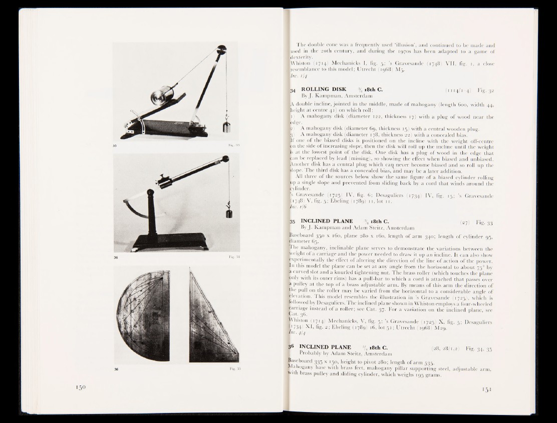
934 ROLLING DISK % 18th G. (1114/1—4) Fig. 32
ByJ. Kampman, Amsterdam
■ A double incline, jointed in the middle, made of mahogany (length 600, width 44,
■ height at centre 41) on which roll:
l i ) A mahogany disk (diameter 122, thickness 17) with a plug of wood near the
■ edge.
k ) A mahogany disk (diameter 6g, thickness 15) with a central wooden plug.
■ 5) A mahogany disk {diameter 178, thickness 22) with a concealed bias.
If one of the biased disks is positioned on the incline with the weight off-centre
■ an the^ side <§|t increasing slope, then the disk will roll up the incline until the weight
fis at the lowest point of the disk. One disk has a plug of wood in the edge that
■ can be replaced by lead .missing), so showing the effect when biased and unbiased.
■ Another disk has a central plug which can never become biased and so roll up the
«lope. The third disk has a concealed bias, Und may be a later addition.
I All three of the sources below show the same figure of a biased cylinder rolling
■ up a single slope and prevented from sliding back by a cord that winds around the
■ cylinder,
IT 3 Gravesande (I7||) IV, fig. 6; Desaguliers (1734) IV, fig. 15; ’s Gravesande
[1748) V, fig. 5; Ebeling (1789) n , 4t>t 11.
Vra. tf$
|3 5 INCLINED PLANE s/4 18th C. (27) Fig. 33
ByJ. Kampman and Adam Steitz, Amsterdam
«Baseboard 35° x 160, plane 280 x 160, length of arm 340; length of cylinder 95,
■ iiameter 65.
■ The mahogany, inclinable plane serves to demonstrate the variations between the
■ 'eight of a carriage and the power needed"'to draw it up an incline. It can also show
■ experimentally the effect of altering the direction of the line of action of the power.
Bn this model the plane can be set at any angle from the horizontal to about 750 by
I 1 curved slot and a knurled tightening nut. The brass roller (which touches the plane
fcnly with its outer rims) has a pull-bar to which a cord is attached that passes over
|jt pulley at the top of a brass adjustable arm. By means of this arm the direction of
■ he pull on the roller may be varied from the horizontal to a considerable angle of
Iplevation. This model resembles the illustration in ’s Gravesande (1725), which is
■ allowed by Desaguliers. The inclined plane shown in Whiston employs a four-wheeled
Carriage instead of a roller; see Cat. 37. For a variation on the inclined plane, see
Kat. 36.
■ Vhiston (1714.) Mechanicks, V, fig., 3:; ’s Gravesande ,(1725) X, fig. 5; Desaguliers
■ ’ 734) XI, fig. 2 ; F.beling (1 789} 16, lot 51; Utrecht {4968) M29.
Whv. 4I4
36 INCLINED PLANE % 18th C. (28,28/1,2) Fig. 34, 35
I Probably by Adam Steitz, Amsterdam
Baseboard 335 x 150, height to pivot 280; length of arm 535.
Kahogany base with brass feet, mahogany pillar supporting steel, adjustable arm,
|vith brass pulley and sliding cylinder, which weighs 195 grams.